Subaru Outback (BR): Security General Description
Subaru Outback (BR) 2010-2015 Service Manual / Body / Security and Locks / Security General Description
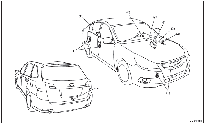
A: COMPONENT
1. DOOR LOCK ASSEMBLY
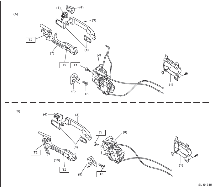
- Front
- Rear
- Inner remote ASSY
- Front door latch and door lock actuator ASSY
- Door outer handle
- Door outer handle cover
- Key cylinder (driver's side only)
- Door outer handle spacer
- Front door outer handle frame ASSY
- Striker
- Rear door latch and door lock actuator ASSY
- Rear door outer handle frame ASSY
Tightening torque: N*m (kgf-m, ft-lb)
T1: 6.5 (0.66, 4.8)
T2: 7.5 (0.76, 5.5)
T3: 18 (1.84, 13.3)
2. REAR GATE LOCK AND TRUNK LID LOCK
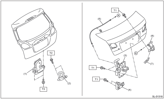
- Rear gate latch and actuator ASSY
- Rear gate striker
- Trunk lid latch and actuator ASSY
- Trunk lid striker
- Cable
- Key cylinder (trunk lid only)
- Clip
Tightening torque: N*m (kgf-m, ft-lb)
T1: 7.5 (0.76, 5.5)
T2: 25 (2.55, 18.4)
T3: 28 (2.86, 20.7)
3. FRONT HOOD LOCK AND REMOTE OPENERS
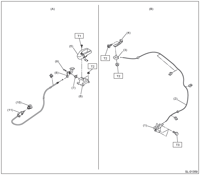
- Fuel lock release
- Hood lock release
- Front hood lock ASSY
- Cable
- Lever ASSY
- Bracket
- Cover
- Bracket
- Spring
- Pull handle ASSY
- Pin
- Holder
- Fuel lock
Tightening torque: N*m (kgf-m, ft-lb)
T1: 4.5 (0.46, 3.3)
T2: 7.5 (0.76, 5.5)
T3: 33 (3.36, 24.3)
4. KEYLESS ENTRY SYSTEM
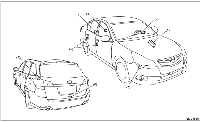
- Body integrated unit
- Power window main switch
- Keyless entry control module
- Trunk lid latch switch (sedan model)
- Door switch
- Rear gate latch switch (OUTBACK model)
- Keyless buzzer
5. SECURITY SYSTEM
- Horn
- Horn relay (in main fuse box)
- Body integrated unit
- Impact sensor (driver's seat instrument panel side) (dealer option)
- Turn signal and hazard module
- Security indicator light (in combination meter)
- Trunk lid latch switch (sedan model)
- Door switch
- Rear gate latch switch (OUTBACK model)
B: CAUTION
- Before disassembling or reassembling parts, always disconnect the battery ground cable from battery.
When replacing the audio, control module and other parts provided with memory functions, record the memory contents before disconnecting the battery ground cable. Otherwise, the memory is cleared.
- Reassemble the parts in the reverse order of disassembly procedure unless otherwise indicated.
- Connect the connectors securely during reassembly.
- After reassembly, make sure that the functional parts operate normally.
- If any immobilizer related part has been replaced, make sure to register the immobilizer.
- Do not use any electrical test equipment on the airbag system wiring harnesses and connector circuits.
- Be careful not to damage the airbag system wiring harness when servicing the ignition key cylinder.
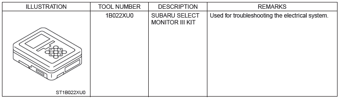
C: PREPARATION TOOL
1. SPECIAL TOOL
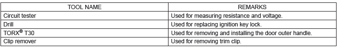
2. GENERAL TOOL
READ NEXT:
 Relay and Fuse, Door Lock Control System
A: LOCATION
NOTE: For other related fuses, refer to the wiring diagram. <Ref. to WI-15, Power Supply Circuit.>
B: INSPECTION
1. CHECK FUSE.
1) Remove the fuse and inspect visually.
2)
Keyless Entry System
A: WIRING DIAGRAM
Refer to "Keyless Entry System" in the wiring diagram. <Ref. to WI-181,
WIRING DIAGRAM, Keyless Entry
System.>
B: ELECTRICAL SPECIFICATION
1. KEYLESS ENTRY CONTROL MODULE
Mo
Front Inner Remote
A: REMOVAL
1) Remove the door trim. <Ref. to EI-60, REMOVAL, Door Trim.>
2) Remove the screws to detach the front inner remote handle.
B: INSTALLATION
1) Before installation, check the followi
SEE MORE:
Drive Pinion Shaft Assembly in Automatic Transmission
A: REMOVAL
1) Remove the transmission assembly from the vehicle.
<Ref. to 5AT-37, REMOVAL, Automatic Transmission Assembly.>
2) Pull out the torque converter assembly. <Ref. to 5AT-63, REMOVAL, Torque Converter Assembly.>
3) Remove the transmission harness connector from stay.
4) Re
Temperature sensors
1) Solar sensor
2) Interior air temperature sensor
The automatic climate control system employs several sensors. These sensors are
delicate. If they are treated incorrectly and become damaged, the system may not
be able to control the interior temperature correctly. To avoid damaging the sen
© 2010-2025 Copyright www.suoutback.com
