Subaru Outback (BR): Ignition Switch Illumination
A: REMOVAL
1) Disconnect the ground cable from battery.
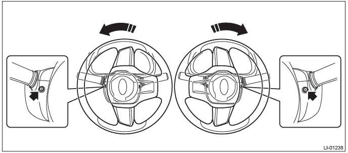
2) Remove the steering column cover.
- Remove the screws by turning the steering wheel to right and left.
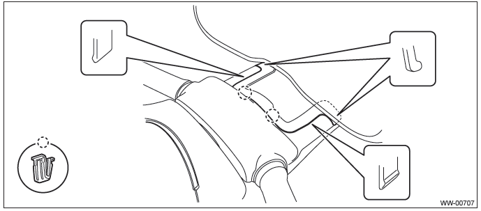
- Release the claws and remove the steering column lower cover.
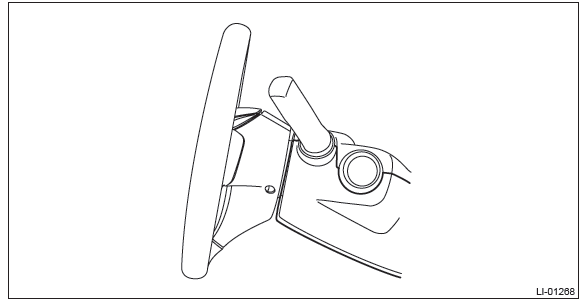
- Separate the steering column upper cover and steering upper cover, and remove the steering column upper cover.
3) Remove the bulb socket and ignition switch illumination bulb.
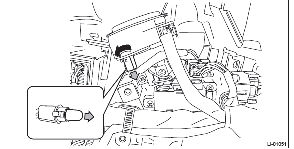
NOTE: If the bulb socket is faulty, replace the ignition key lock. <Ref. to SL-58, Ignition Key Lock.>
B: INSTALLATION
Install each part in the reverse order of removal.
C: INSPECTION
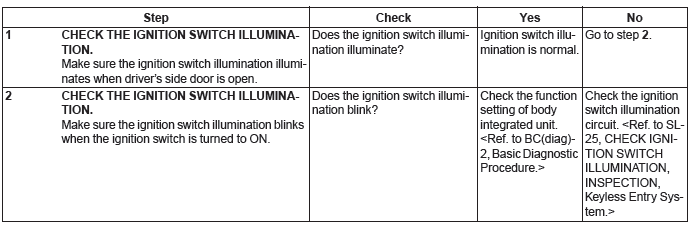
Day Time Running Resistor
A: REMOVAL
1) Remove the front bumper face assembly. <Ref. to EI-39, REMOVAL, Front Bumper.>
2) Remove the daytime running resistor.
- Disconnect the connector.
- Remove the bolt, and remove the daytime running resistor.
B: INSTALLATION
1) Install each part in the reverse order of removal.
Tightening torque:
Daytime running resistor: 7.5 N*m (0.76 kgf-m, 5.5 ft-lb)
2) Adjust the fog light beam. (Model with fog light) <Ref. to LI-41, FOG LIGHT AIMING, ADJUSTMENT, Front Fog Light Assembly.>
Reflex Reflector
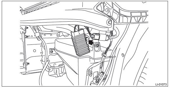
A: REMOVAL
From behind the bumper, release the claws and remove the reflex reflector.
B: INSTALLATION
Install each part in the reverse order of removal.
Door Switch
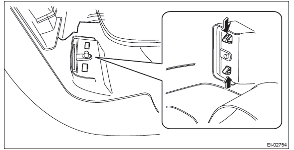
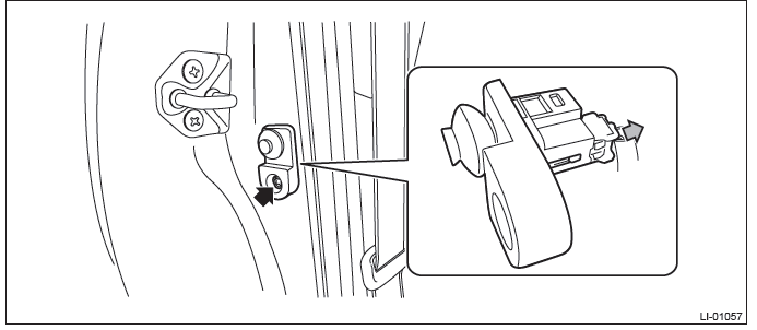
A: REMOVAL
1) Disconnect the ground cable from battery.
2) Remove the door switch.
- Remove the screws, and pull out the door switch.
- Disconnect the connector and remove the door switch.
B: INSTALLATION
Install each part in the reverse order of removal.
C: INSPECTION
Refer to "CHECK DOOR SWITCH" of "Interior Light System". <Ref. to LI-16, CHECK DOOR SWITCH., INSPECTION, Interior Light System.>
READ NEXT:
 General Description of Wiper and Washer Systems
A: SPECIFICATION
B: COMPONENT
1. FRONT WIPER
Wiper rubber
Wiper blade ASSY
Wiper arm ASSY
Pivot cover B
Wiper link ASSY
Pivot cover C
Wiper motor assembly
Wiper and Washer System
A: WIRING DIAGRAM
1. WIPER AND WASHER (FRONT)
Refer to "Front Wiper and Washer System" in the wiring diagram. <Ref. to
WI-169, WIRING DIAGRAM, Front
Wiper and Washer System.>
2. WIPER AND WASHE
SEE MORE:
Charge warning light
If this light illuminates when the engine is running, it may indicate that the
charging system is not working properly.
If the light illuminates while driving or does not turn off after the engine
starts, stop the engine at the first safe opportunity and check the alternator belt.
If the be
Rear Stabilizer
A: REMOVAL
1) Lift up the vehicle, and then remove the rear wheels.
2) Remove the rear stabilizer.
Remove left and right stabilizer links.
Detach the stabilizer clamp and remove the rear stabilizer.
B: INSTALLATION
CAUTION:
Be sure to use a new flange nut and self-locking nut.
Always tighte
