Subaru Outback (BR): General Description of Wiper and Washer Systems
A: SPECIFICATION
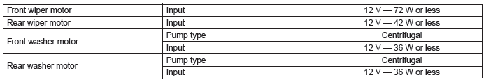
B: COMPONENT
1. FRONT WIPER
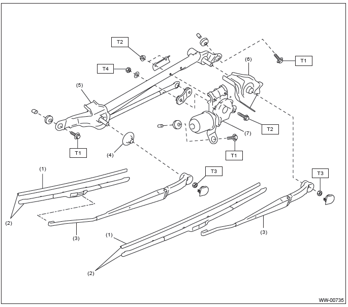
- Wiper rubber
- Wiper blade ASSY
- Wiper arm ASSY
- Pivot cover B
- Wiper link ASSY
- Pivot cover C
- Wiper motor assembly
Tightening torque: N*m (kgf-m, ft-lb)
T1: 6 (0.61, 4.4)
T2: 7.5 (0.76, 5.5)
T3: 22 (2.24, 16.2)
T4: 32.1 (3.27, 23.7)
2. REAR WIPER
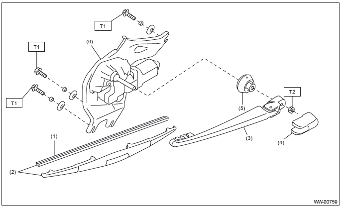
- Wiper rubber
- Wiper blade ASSY
- Wiper arm
- Wiper arm cover
- Pivot cap
- Wiper motor ASSY
Tightening torque: N*m (kgf-m, ft-lb)
T1: 7 (0.71, 5.2)
T2: 8 (0.82, 5.9)
3. WASHER TANK
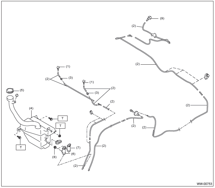
- Front washer nozzle
- Washer hose
- Check valve
- Washer tank
- Washer tank cap
- Front washer motor
- Rear washer motor (OUTBACK model only)
- Grommet
- Rear washer nozzle (OUTBACK model only)
Tightening torque: N*m (kgf-m, ft-lb)
T: 6 (0.61, 4.4)
C: CAUTION
- Connect the connectors and hoses securely during reassembly.
- After reassembly, make sure functional parts operates smoothly.
- Be careful with the airbag system wiring harness which passes near electrical parts and switches.
- Yellow connectors and harnesses with yellow tapes around them are the connectors and harnesses for the airbag system. Using a tester above such circuits may cause malfunction of airbag system. Follow the cautions for the airbag system in this case. <Ref. to AB-9, CAUTION, General Description.>
- When connecting the pipe hoses, be careful not to cause bend or blockage.
- If even a small amount of silicon oil or grease enters tank and washer fluid passages, an oil film will be formed on the glass and will cause the wiper to chatter and judder. Make sure that no oil comes into contact with the system.
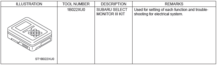
D: PREPARATION TOOL
1. SPECIAL TOOL
2. GENERAL TOOL

NOTE: Refer to the data described below, prepare the materials to make a front washer nozzle adjustment tool.
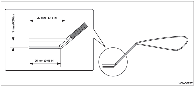
Materials
- Vertebra of wiper blade which is to be discarded
- Vinyl tape
Steps of making a front washer nozzle adjustment tool
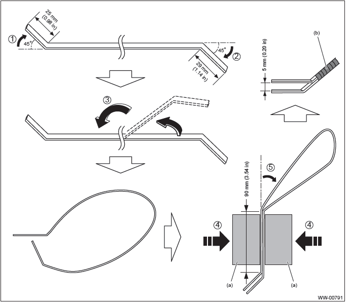
1. Bend the vertebra at the position 25 mm (0.98 in) away from its end by 45º.
2. Bend the vertebra at the position 29 mm (1.14 in) away from the other end by 45º.
3. Double up the vertebra so that the longer end (29 mm (1.14 in) ) comes upward.
4. Secure the vertebra with a vise (a) so that the tip clearance becomes 5 mm (0.20 in).
5. Bend the vertebra at the position approximately 90 mm (3.54 in) away from the bending point for the longer end.
6. Check that the tip clearance is 5 mm (0.20 in), and secure the vertebra with vinyl tape (b).
READ NEXT:
 Wiper and Washer System
A: WIRING DIAGRAM
1. WIPER AND WASHER (FRONT)
Refer to "Front Wiper and Washer System" in the wiring diagram. <Ref. to
WI-169, WIRING DIAGRAM, Front
Wiper and Washer System.>
2. WIPER AND WASHE
Wiper Blade
A: REMOVAL
1. FRONT
Remove the blade assembly.
1) Lift up the locking clip (A).
2) Turn the blade assembly in the arrow direction.
3) Press the arm in.
4) Pull out the arm while lifting it, and rem
Front Wiper Motor and Link
A: REMOVAL
1) Disconnect the ground cable from battery.
2) Remove the front wiper arm assembly.
CAUTION:
Follow the steps below when standing up the wiper arm. Not following the steps
may cause cont
SEE MORE:
Preset buttons
How to preset channels
1. Press the “SAT” button to select SAT1, SAT2 and SAT3 reception.
2. Select the desired channel.
3. Press one of the preset buttons for more than 1.5 seconds to store the channel.
If the button is pressed for less than 1.5 seconds, the preceding selection will
rema
Stop Light Switch
A: REMOVAL
1) Disconnect the ground cable from battery.
2) Remove the instrument panel lower cover.
Remove the clips, and remove the instrument panel side cover LH.
Remove the clips and data link connector, and remove the instrument
panel lower cover under.
Remove the bolts, and remove
