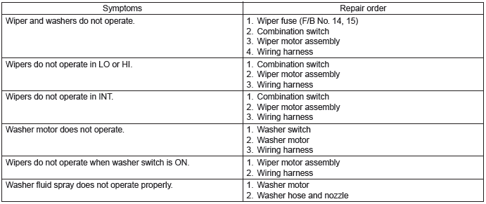
Subaru Outback (BR): Wiper and Washer System
A: WIRING DIAGRAM
1. WIPER AND WASHER (FRONT)
Refer to "Front Wiper and Washer System" in the wiring diagram. <Ref. to WI-169, WIRING DIAGRAM, Front Wiper and Washer System.>
2. WIPER AND WASHER (REAR)
Refer to "Rear Wiper and Washer System" in the wiring diagram. <Ref. to WI-219, WIRING DIAGRAM, Rear Wiper and Washer System.>
B: INSPECTION
C: NOTE
For procedure of each component of the wiper and washer system, refer to the respective sections.
- Combination switch (wiper): <Ref. to WW-9, Combination Switch (Wiper).>
- Wiper blade: <Ref. to WW-16, Wiper Blade.>
- Washer tank and motor: <Ref. to WW-19, Washer Tank and Motor.>
- Front wiper arm: <Ref. to WW-24, Front Wiper Arm.>
- Front wiper motor and link: <Ref. to WW-25, Front Wiper Motor and Link.>
- Front washer nozzle: <Ref. to WW-31, Front Washer Nozzle.>
- Rear wiper arm: <Ref. to WW-36, Rear Wiper Arm.>
- Rear wiper motor: <Ref. to WW-38, Rear Wiper Motor.>
- Rear washer nozzle: <Ref. to WW-43, Rear Washer.>
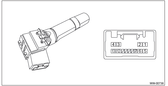
Combination Switch (Wiper)
A: REMOVAL
1) Disconnect the ground cable from battery.
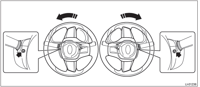
2) Remove the steering column cover.
- Remove the screws by turning the steering wheel to right and left.
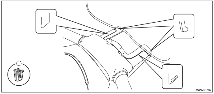
- Release the claws and remove the steering column lower cover.
- Separate the steering column upper cover and steering upper cover, and remove the steering column upper cover.
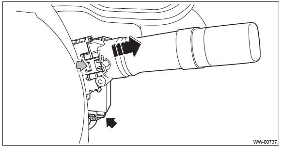
3) Remove the wiper switch assembly.
- Disconnect the connector from wiper switch.
- Release the claws, and pull out the wiper switch assembly.
CAUTION: Do not press the claws with excessive force. They may be damaged.
B: INSTALLATION
Install each part in the reverse order of removal.
C: INSPECTION
1. INSPECTION OF SWITCH UNIT
1) Operate the switches to check the continuity between terminals.
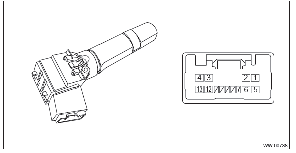
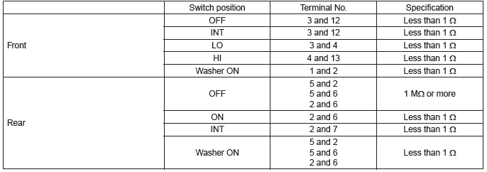
2) Replace the switch if the inspection result is not within the standard value.
2. FRONT WIPER
1) Check with Subaru Select Monitor
- Check the input signal when the front wiper switch is turned to LO or HI, using the current data display of body integrated unit.
- Does the input signal change corresponding to the switch operation?
- Yes → Finish the diagnosis.
- No →
- Check the harness.
- Check the input voltage of body integrated unit.
Connector & terminal
(B280) No. 2 (+) - Chassis ground (-):
- Replace the body integrated unit. <Ref. to SL-71, Body Integrated Unit.>
2) Check the intermittent operation (inspection of the wiper switch alone)
- Set the voltage meter between terminal No. 4 (+) and No. 3 (-).
- Connect the battery to connector. (Terminal No. 4 (+), terminal No. 2 & 3 (-) )
- Turn the front wiper switch to INT.
- Connect the battery (+) to the terminal No. 4 for 5 seconds.
- Connect the battery (-) to the terminal No. 2 and check the voltage between terminal No. 4 - terminal No. 3 during intermittent operation.
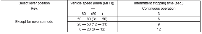
- Perform step (1) to (5) above when intermittent control switch is in MIN or MAX, and replace the switch if the operation is not as specified.
Intermittent stationary time
MIN: Approx. 2 seconds
MAX: Approx. 16 seconds
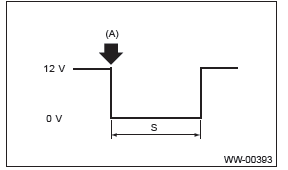
(A): Connect the battery (-) to the terminal No. 12.
S: Intermittent downtime (sec.)
3. REAR WIPER
1) Check input of body integrated unit.
Check the input signal when the rear wiper switch is operated using Subaru Select Monitor.
- Turn the ignition switch to ON.
- Operate the rear wiper switch to each position of ON, INT and Washer ON.
- Does the input signal change corresponding to the switch operation?
- Yes → Go to step 4.
- No → Go to step 2.
2) Check harness.
- Turn the ignition switch to OFF, disconnect the ground cable from battery.
- Disconnect the connector of body integrated unit and wiper switch.
- Measure the resistance between body integrated unit and wiper switch.
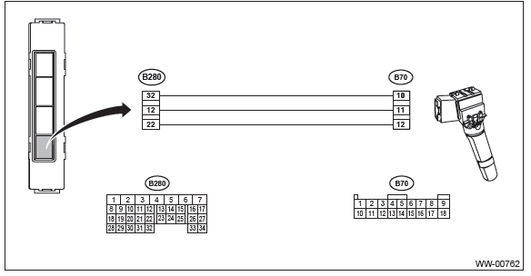
Connector & terminal
(B280) No. 32 - (B70) No. 10:
(B280) No. 12 - (B70) No. 11:
(B280) No. 22 - (B70) No. 12:
- Is the resistance less than 10 Ω?
- Yes → Go to step 3.
- No → Repair the harness between the body integrated unit and wiper switch.
3) Check input voltage of body integrated unit.
- Connect the ground cable to battery.
- Turn the ignition switch to ON and check the input voltage of body integrated unit.
Connector & terminal
(B280) No. 5 (+) - Chassis ground (-):
(i171) No. 17 (+) - Chassis ground (-):
- Is the voltage 10 V or more?
- Yes → Go to step 4.
- No → Check the harness and fuse.
4) Check output of body integrated unit.
Check the output signal when the rear wiper switch is operated using Subaru Select Monitor.
- Turn the ignition switch to ON.
- Operate the rear wiper switch to ON and Washer ON.
- When the operation in step (2) is performed, check the output signal of body integrated unit to rear wiper motor.
- When the rear wiper switch is set to ON, is ON output continuous? Also,
when the washer is set to ON,
is ON output?
- Yes → Go to step 5.
- No → Replace the body integrated unit. <Ref. to SL-71, Body Integrated Unit.>
5) Check output of body integrated unit.
Check the output signal when the rear wiper switch is operated using Subaru Select Monitor.
- Turn the ignition switch to ON.
- Set the rear wiper switch to INT.
- When the operation in step (2) is performed, check the output signal of body integrated unit.
- When the rear wiper switch is set to INT, is ON/OFF output repeated? (INT
OFF time (when vehicle
parked): 12 seconds)
- Yes → Go to step 8.
- No → Go to step 6.
6) Check harness between body integrated unit and rear wiper motor.
- Turn the ignition switch to OFF, disconnect the ground cable from battery.
- Disconnect the connector of body integrated unit and wiper switch.
- Measure the resistance between the harness connector terminals of the body integrated unit and rear wiper motor.
Connector & terminal
(B280) No. 6 - (D43) No. 2:
- Is the resistance less than 10 Ω?
- Yes → Go to step 7.
- No → Repair the open circuit of the harness between body integrated unit and rear wiper motor.
7) Check stop position circuit of the rear wiper motor.
- Disconnect the harness connector of the rear wiper motor.
- Check the continuity of the circuit of rear wiper motor stop position.
Connector & terminal
(D43) No. 1 (+) - (D43) No. 4 (-):
- Is there continuity between terminals?
- Yes → Go to step 8.
- No → Replace the rear wiper motor assembly.
8) Check power supply circuit of the rear wiper motor.
- Disconnect the harness connector of the rear wiper motor.
- Turn the ignition switch to ON.
- Measure the voltage between the rear wiper motor harness connector terminal and chassis ground.
Connector & terminal
(D43) No. 3 (+) - Chassis ground (-):
- Is the voltage 10 V or more?
- Yes → Go to step 9.
- No → Check the fuse (No. 27 in main fuse box).
9) Check ground circuit of rear wiper motor.
- Turn the ignition switch to OFF.
- Measure the resistance between the rear wiper motor harness connector terminal and chassis ground.
Connector & terminal
(D43) No. 4 - Chassis ground:
- Is the resistance less than 10 Ω?
- Yes → Go to step 10.
- No → Repair the open circuit of the rear wiper motor ground circuit.
10) Check harness between body integrated unit and rear wiper motor.
- Turn the ignition switch to OFF.
- Disconnect the harness connector of body integrated unit.
- Disconnect the harness connector of the rear wiper motor.
- Measure the resistance between the harness connector terminals of the body integrated unit and rear wiper motor.
Connector & terminal
(B280) No. 7 - (D43) No. 1:
- Is the resistance less than 10 Ω?
- Yes → Go to step 11.
- No → Repair the open circuit of the harness between body integrated unit and rear wiper motor.
11) Check output of body integrated unit.
- Connect the harness connector of body integrated unit.
- Disconnect the connector of the rear wiper motor.
- Turn the ignition switch to ON.
- Measure the voltage between rear wiper motor connector and chassis ground.
Connector & terminal
(D43) No. 2 (+) - Chassis ground (-):
- Is the voltage less than 1.5 V when the rear wiper switch is OFF, and is
the voltage 10 V or more when
the rear wiper switch is ON?
- Yes → Go to step 12.
- No → Replace the body integrated unit. <Ref. to SL-71, Body Integrated Unit.>
12) Check operation of rear wiper motor.
- Remove the rear wiper motor.
- Check the rear wiper motor. <Ref. to WW-42, INSPECTION, Rear Wiper Motor.>
- Does the rear wiper motor rotate normally?
- Yes → Finished.
- No → Replace the rear wiper motor assembly.
NOTE: Rear wiper intermittent time
READ NEXT:
 Wiper Blade
A: REMOVAL
1. FRONT
Remove the blade assembly.
1) Lift up the locking clip (A).
2) Turn the blade assembly in the arrow direction.
3) Press the arm in.
4) Pull out the arm while lifting it, and rem
Front Wiper Motor and Link
A: REMOVAL
1) Disconnect the ground cable from battery.
2) Remove the front wiper arm assembly.
CAUTION:
Follow the steps below when standing up the wiper arm. Not following the steps
may cause cont
Rear Wiper Arm
A: REMOVAL
1) Pull up the wiper arm cover.
2) Remove the nut and remove the wiper arm.
B: INSTALLATION
1) Install in the reverse order of removal.
2) Operate the rear wiper once.
3) Align the blad
SEE MORE:
Replacement of brake pad and lining
CAUTION
If you continue to drive despite the scraping noise from the audible brake pad
wear indicator, it will result in the need for costly brake rotor repair or replacement.
The right front disc brake and the right rear disc brake have audible wear indicators
on the brake pads. If the brak
Installing carrying attachments on the crossbars
When installing any carrying attachment such as a bike carrier, ski carrier,
kayak carrier, cargo basket, etc. on the crossbars, follow the manufacturer’s instructions
and make sure that the attachment is securely fixed to the crossbars. Use only genuine
SUBARU attachments. A set of the cros
