Subaru Outback (BR): Operating Cylinder
A: REMOVAL
NOTE: The illustration below is suitable for every model.
Perform the same procedures for the other models.
1) Remove the collector cover. (turbo model)
2) Remove the air intake boot assembly. (non-turbo model) <Ref. to IN(H4SO)-8, REMOVAL, Air Intake Boot.>
3) Remove the intercooler. (turbo model) <Ref. to IN(H4DOTC)-17, REMOVAL, Intercooler.>
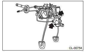
4) Disconnect the clutch hose from the operating cylinder.
CAUTION:
- Cover the hose joint to prevent the clutch fluid from flowing out.
- Do not loosen or remove the cap bolt at the rear end of operating cylinder. (turbo model)
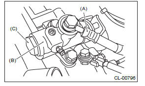
- Clutch hose
- Operating cylinder
- Cap bolt
5) Remove the operating cylinder from the transmission.
B: INSTALLATION
NOTE:
- The illustration below is suitable for every model.
Perform the same procedures for the other models.
- Use a new gasket.
- Be sure to install the clutch hose with the mark side facing upward.
- Be careful not to twist the clutch hose during installation.
- Before installing the operating cylinder, apply grease to the contact point of the release lever and operating cylinder.
Grease
NICHIMOLY N-130 or equivalent
1) Install in the reverse order of removal.
Tightening torque:
T1: 18 N*m (1.8 kgf-m, 13.3 ft-lb)
T2: 37 N*m (3.8 kgf-m, 27.3 ft-lb)
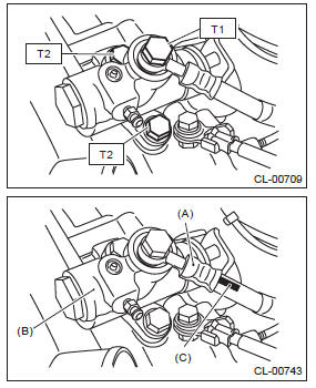
- Clutch hose
- Operating cylinder
- Mark
2) After bleeding air from the operating cylinder, ensure that the clutch operates properly. <Ref. to CL-25, PROCEDURE, Clutch Fluid Air Bleeding.>
3) When the operating cylinder has been replaced or removed, perform the clutch sensor calibration mode. <Ref. to PB(diag)-20, CLUTCH SENSOR CALIBRATION MODE, OPERATION, Subaru Select Monitor.>
NOTE: If necessary, perform the clutch meet position setting.
<Ref. to PB(diag)-20, CLUTCH ENGAGEMENT POSITION SETTING, OPERATION, Subaru Select Monitor.>
C: DISASSEMBLY
NOTE: The illustration shows a representing model. Perform the same procedures for the other models.
1) Remove the boot and push rod.
2) Apply compressed air through clutch hose attachment hole.
NOTE: Face the piston hole down and place a piece of wood underneath to prevent the piston from popping out.
3) Separate the piston and piston spring.
D: ASSEMBLY
NOTE:
- The illustration shows a representing model.
Perform the same procedures for the other models.
- During assembly, apply hydraulic oil to all parts.
Recommended clutch fluid: New FMVSS No. 116 DOT3
1) Install the piston spring onto the piston.
2) Insert piston to the operating cylinder.
3) Install push rod to the boot.
4) Install boot and push rod to the operating cylinder.
E: INSPECTION
1) Check that the operating cylinder is not damaged.
Replace the operating cylinder if it is damaged.
2) Check the clutch fluid leakage on the operating cylinder or the boot for damage. Replace the operating cylinder if clutch fluid leaks or boot damages are noted.
Master Cylinder
A: REMOVAL
1) Disconnect the ground cable from battery.
2) Remove the collector cover. (turbo model) 3) Thoroughly drain the clutch fluid from the reservoir tank.
4) Remove the instrument panel lower cover. <Ref. to EI-64, REMOVAL, Instrument Panel Lower Cover.>
5) Remove the pedal assembly. <Ref. to CL-26, REMOVAL, Clutch Pedal.>
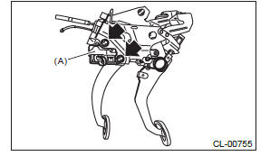
6) Remove the clip and clevis pin, and then separate the push rod of the master cylinder from clutch pedal.
- Clevis pin
- Clip
- Push rod
7) Disconnect the clutch stroke sensor connector.
8) Remove the clutch pipe from the master cylinder.
9) Remove the master cylinder from the pedal bracket.
- Master cylinder
B: INSTALLATION
1) Install the master cylinder to the pedal assembly.
Tightening torque: 18 N*m (1.8 kgf-m, 13.3 ft-lb)
- Master cylinder
2) Connect the clutch pipes to the master cylinder.
Tightening torque: 15 N*m (1.5 kgf-m, 11.1 ft-lb)
3) Connect the clutch stroke sensor connector.
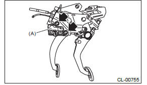
4) Connect the push rod of the master cylinder to the clutch pedal, and install the clevis pin and clip.
CAUTION: Always use a new clevis pin.
NOTE: Apply grease to the clevis pin.
- Clevis pin
- Clip
- Push rod
5) Install the pedal assembly. <Ref. to CL-26, INSTALLATION, Clutch Pedal.>
6) Install the instrument panel lower cover. <Ref. to EI-65, INSTALLATION, Instrument Panel Lower Cover.>
7) Connect the battery ground terminal.
8) Fill the recommended clutch fluid. <Ref. to CL- 24, Clutch Fluid.>
9) After bleeding air from the clutch system, ensure that the clutch operates properly. <Ref. to CL-25, Clutch Fluid Air Bleeding.>
10) Install the collector cover. (turbo model)
11) When the clutch master cylinder assembly has been replaced, perform the clutch sensor calibration mode. <Ref. to PB(diag)-20, CLUTCH SENSOR CALIBRATION MODE, OPERATION, Subaru Select Monitor.>
NOTE: If necessary, perform the clutch meet position setting.
<Ref. to PB(diag)-20, CLUTCH ENGAGEMENT POSITION SETTING, OPERATION, Subaru Select Monitor.>
C: INSPECTION
If any damage, deformation, wear, swelling, rust or other faults are found on the master cylinder assembly, reservoir tank, clutch damper, clutch pipe and clutch hose, replace the faulty part.
READ NEXT:
 Clutch Pipe and Hose
A: REMOVAL
1) Disconnect the ground cable from battery.
2) Remove the collector cover. (turbo model)
3) Remove the air intake boot assembly. (non-turbo
model) <Ref. to IN(H4SO)-8, REMOVAL, Air Int
Clutch Fluid
A: INSPECTION
1) Park the vehicle on a level surface.
2) Check the clutch fluid level using the scale on
the outside of the reservoir tank. If the clutch fluid
level is below "MIN", fill the clutch f
Clutch Pedal
A: REMOVAL
1) Disconnect the ground cable from battery.
2) Remove the collector cover. (turbo model)
3) Remove the air intake boot assembly. (non-turbo
model) <Ref. to IN(H4SO)-8, INSTALLATION,
SEE MORE:
Exhaust
General Description
A: COMPONENT
Models other than C6 model
C6 model
Gasket
Spring
Chamber
Rear exhaust pipe
Cushion rubber (without protrusion)
Self-locking nut
Gasket
Muffler
Bolt
Center exhaust pipe front upper
cover
Rear catalytic converter upper
cover
Center exhaust pipe
Rear Drive Shaft, General Diagnostic Table
A: REMOVAL
1) Lift up the vehicle, and then remove the rear wheels.
2) Remove the axle nut.
CAUTION: Do not loosen the axle nut while the rear axle is loaded. Doing so may damage the hub bearing.
Lift the crimped section of axle nut.
Remove the axle nut using a socket wrench while de
