Subaru Outback (BR): Outer Mirror Assembly
A: REMOVAL
1) Remove the front door trim. <Ref. to EI-60, FRONT DOOR, REMOVAL, Door Trim.>
2) Remove the outer mirror assembly.
- Disconnect the connector.
- Remove the bolts to remove outer mirror assembly.

B: INSTALLATION
Install each part in the reverse order of removal.
Tightening torque:
Outer mirror assembly: 4.5 N*m (0.46 kgf-m, 3.3 ft-lb)
C: INSPECTION
1) Disconnect the outer mirror connector.
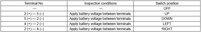
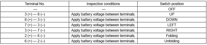
2) Apply battery voltage between the outer mirror connector terminals and check the mirror operation.
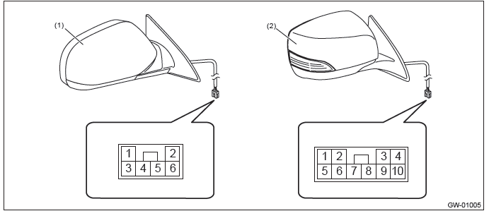
- Model without electric retractable mirror
- Model with electric retractable mirror
- Model without electric retractable mirror
- Model with electric retractable mirror
3) If it does not operate normally, replace the outer mirror assembly.
Outer Mirror
A: REPLACEMENT
1. MODEL WITHOUT ELECTRIC RETRACTABLE MIRROR
CAUTION:
- When removing the mirror, be careful not to damage the back surface of mirror with a flat tip screwdriver.
- When installing the mirror, insert the connector and clip securely.
1) Operate the remote control mirror switch to face the mirror surface upward.
2) Disconnect the ground cable from battery.
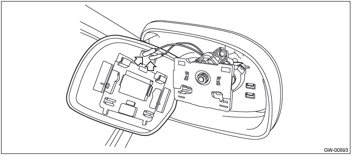
3) Remove the outer mirror.
- Disconnect the clips using a flat tip screwdriver.
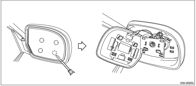
- Disconnect the mirror heater connector. (Model with mirror heater)
4) Install the outer mirror in the reverse order of removal.
2. MODEL WITH ELECTRIC RETRACTABLE MIRROR
CAUTION:
- When removing the mirror, be careful not to damage the back surface of mirror with a flat tip screwdriver.
- When installing the mirror, insert the connector and clip securely.
1) Operate the remote control mirror switch to face the mirror surface upward.
2) Disconnect the ground cable from battery.
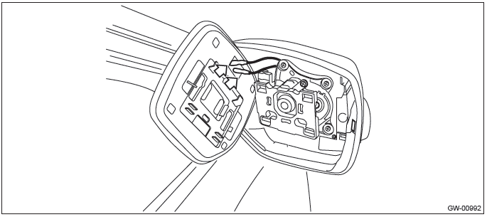
3) Remove the outer mirror.
- Using a flat tip screwdriver, release the clips then remove the outer mirror by sliding downward.
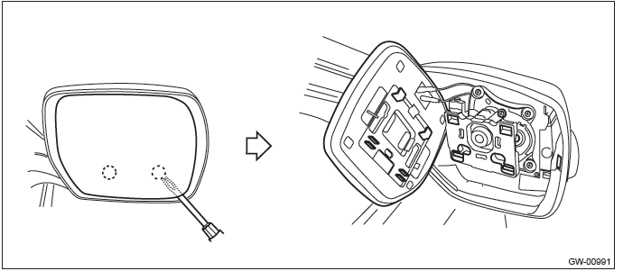
- Disconnect the mirror heater connector. (Model with mirror heater)
4) Install the outer mirror in the reverse order of removal.
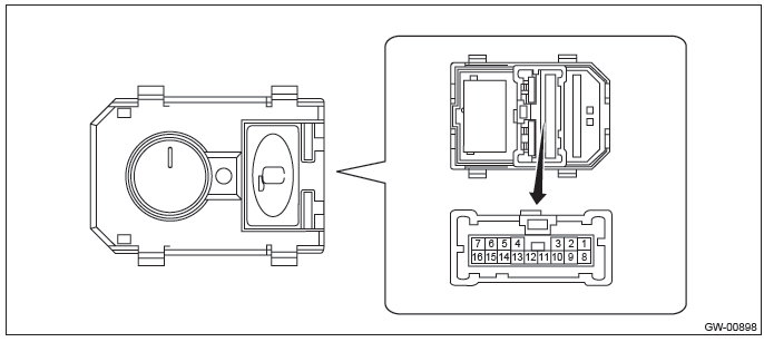
Remote Control Mirror Switch
A: REMOVAL
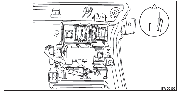
1) Remove the instrument panel lower cover. <Ref. to EI-64, REMOVAL, Instrument Panel Lower Cover.>
2) Disconnect the claws and then remove the remote control mirror switch.
B: INSTALLATION
Install each part in the reverse order of removal.
C: INSPECTION
1) Disconnect the remote control mirror switch connector.
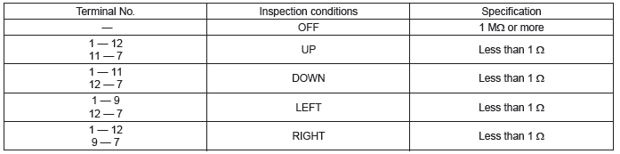
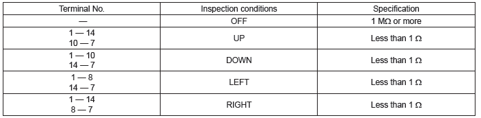
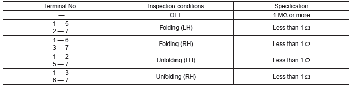
2) Check the resistance between remote control mirror switch terminals.
Preparation tool: Circuit tester
- Changeover switch RH
- Changeover switch LH
- Folding switch (model with electric retractable mirror)
3) Replace the remote control mirror switch if the inspection result is not within the standard value.
READ NEXT:
 Rear Door Glass
A: REMOVAL
1) Remove the rear door trim. <Ref. to EI-61, REAR DOOR, REMOVAL, Door Trim.>
2) Remove the sealing cover.
CAUTION:
Carefully remove the butyl tape. Excessive force will easily bre
Windshield Glass
A: REMOVAL
1. USING WINDSHIELD GLASS KNIFE
1) Disconnect the ground cable from battery. (Models with wiper deicer)
2) Remove the front pillar trim. <Ref. to EI-102, REMOVAL, Upper Inner Trim.>
Rear Gate Glass
A: REMOVAL
1) Disconnect the ground cable from battery.
2) Remove the rear gate trim. <Ref. to EI-160, REMOVAL, Rear Gate Trim.>
3) Remove the rear gate garnish. <Ref. to EI-164, REMOVAL, R
SEE MORE:
Vehicle Dynamics Control warning light/Vehicle Dynamics Control operation indicator
light
The light illuminates when the ignition switch is turned to the “ON” position
and turns off several seconds after the engine has started. This lighting pattern
indicates that the Vehicle Dynamics Control system is operating normally.
Vehicle Dynamics Control warning light
CAUTION
Becaus
General Description of Trim
A: COMPONENT
1. FRONT UNDER COVER
Small type
Medium type
Large type
Tightening torque: N*m (kgf-m, ft-lb)
T: 17.5 (1.78, 12.9)
2. FLOOR UNDER PROTECTOR
Tightening torque: N*m (kgf-m, ft-lb)
T: 7.5 (0.76, 5.5)
3. FUEL TANK PROTECTOR
Fuel tank protector RH
F
