Subaru Outback (BR): Roll Connector
A: REMOVAL
1) Position the front wheels straight ahead. (After moving a vehicle 5 m (16 ft) or more with front wheels positioned straight ahead, make sure that the vehicle moves straight ahead.)
2) Turn the ignition switch to OFF.
3) Disconnect the ground cable from battery and wait for at least 60 seconds before starting work.
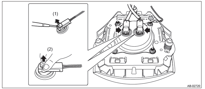
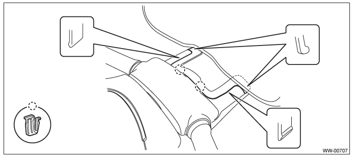
4) Remove the driver's airbag module assembly.
- Using a hexagon wrench etc. wrapped by protective tape, insert the snap pins and release the locks (3 locations).
- Disconnect the horn harness and airbag connector and remove the airbag module assembly. <Ref. to AB-21, DRIVER'S AIRBAG MODULE, CURTAIN AIRBAG MODULE & PRETENSIONER, PROCEDURE, Airbag Connector.>
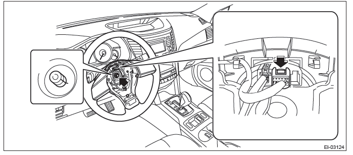
5) Remove the steering wheel.
CAUTION:
- Always use the steering wheel puller for removal to avoid deforming the steering wheel.
- If the steering wheel has been removed, make sure that the roll connector is not turned from the original position.
- Disconnect the connector and remove the nut.
- Put alignment marks and remove the steering wheel.
6) Remove the steering column cover.
- Lower the lever of the steering column.
- Release the claws and remove the screws, then detach the steering column lower cover.
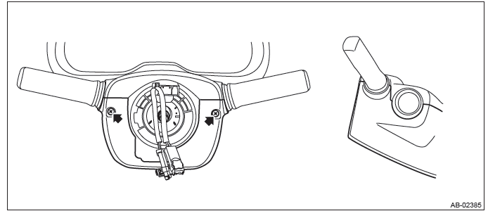
- Separate the steering column upper cover and steering upper cover, and remove the steering column upper cover.
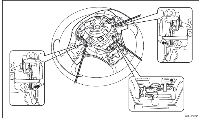
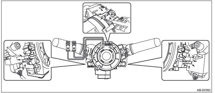
7) Remove the roll connector.
CAUTION: Make sure that the roll connector is not turned from the original position.
- Disconnect the connector under the roll connector.
- Release the claws and remove the roll connector.
B: INSTALLATION
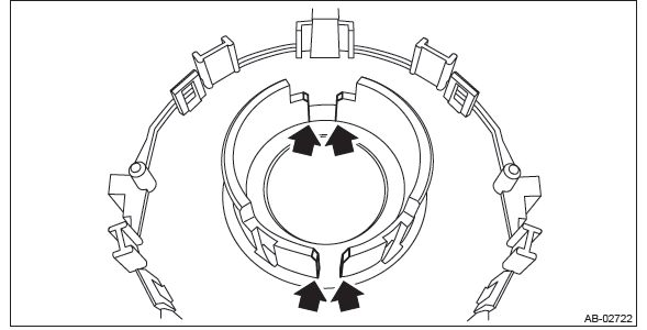
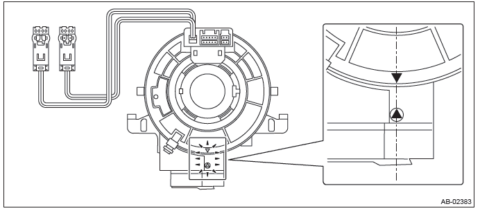
1) Before attaching a new roll connector, apply a thin coat of grease contained in the connector onto the areas shown by the arrows.
2) Install each part in the reverse order of removal.
3) Before installing steering wheel, be sure to adjust the direction of roll connector with steering. <Ref. to AB- 101, ADJUSTMENT, Roll Connector.>
Tightening torque:
Steering wheel: 39 N*m (3.98 kgf-m, 28.8 ft-lb)
Clearance:
Between column cover and steering wheel: 2 - 4 mm (0.08 - 0.16 in)
C: INSPECTION
1. VISUAL INSPECTION
Check for the following, and replace the damaged parts with new parts.
- Combination switch is cracked or deformed.
- Roll connector is cracked or deformed.
2. UNIT INSPECTION OF ROLL CONNECTOR
CAUTION:
- Do not rotate the roll connector to more than the specified number of turns. Otherwise, the roll connector internal wire may be broken.
- When determining the end stop, rotate the connector slowly without applying excessive force. Applying excessive force at the end stop may break the internal wire.
1) Adjust the roll connector. <Ref. to AB-101, ADJUSTMENT, Roll Connector.>
2) Set the roll connector to the central position.
3) Connect the test harness to the connector E and connector F.
Preparation tool: Test harness N (98299SA000), Test harness Q (98299SA040)
- Connector E - Test harness N (1N)
- Connector F - Test harness Q (1Q)
4) With the following conditions, check the resistance between the test harness connector terminals.
- Perform the check with the roll connector centered (front wheels direct straightforward).
- Rotate the roll connector counterclockwise from the center (front wheels direct straightforward) to an end stop. Then, perform the check while rotating it clockwise to approximately 4.5 turns.
Preparation tool: Circuit tester
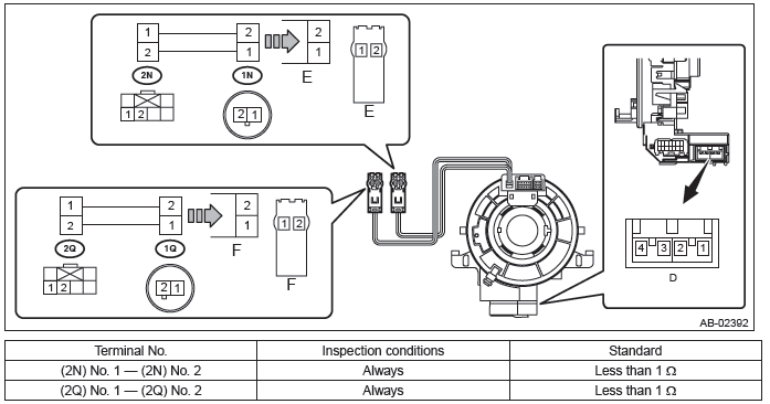
NOTE: The connector D is designed to short the terminals D1/D2 and D3/D4 when disconnected.
5) Replace the roll connector with a new part if the inspection result is not within the standard value.
D: ADJUSTMENT
CAUTION:
- Do not rotate the roll connector to more than the specified number of turns. Otherwise, the roll connector internal wire may be broken.
- When determining the end stop, rotate the connector slowly without applying excessive force. Applying excessive force at the end stop may break the internal wire.
1) Check that front wheels are positioned in straight ahead direction.
2) Rotate the roll connector counterclockwise until it stops.
3) Rotate the roll connector clockwise approx. 3 turns until " "
marks are aligned.
"
marks are aligned.
READ NEXT:
 Basic Diagnostic Procedure of Airbag System
A: PROCEDURE
Check List for Interview
A: CHECK
Identification
A: PROCEDURE
Identify the vehicle using the chassis number, part number of the airbag control module or Subaru Select Monitor.
Airbag Connector, Diagnostic Trouble Code
A: PROCEDURE
For operation procedures, refer to "Airbag Connector" of Airbag System. <Ref. to AB-18, Airbag Connector.>
Airbag Control Module I/O Signal
A: ELECTRICAL SPECIFICATION
SEE MORE:
Front passenger’s SRS frontal airbag
The front passenger’s SRS frontal airbag uses a dual stage inflator. The inflator
operates in different ways depending on the severity of impact.
The total load on the seat is monitored by the passenger’s occupant detection
system weight sensor under the seat.
Using the total seat load and
Oil Temperature Sensor
A: REMOVAL
1) Disconnect the ground cable from battery.
2) Remove the cover (A) and clip (B) from air intake
boot assembly.
3) Loosen the clamp (A) which connects the air intake
boot assembly and air cleaner case.
4) Loosen the clamp (B) which connects the air intake
boot assembly and throttle bo
