Subaru Outback (BR): Seat Heater System
A: REMOVAL
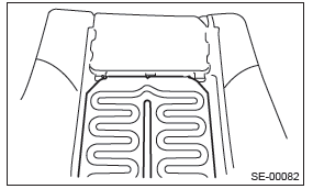
1. SEAT HEATER UNIT
1) Remove the front seats. <Ref. to SE-10, REMOVAL, Front Seat.>
2) Remove the backrest cover of front seat and seat cushion cover. <Ref. to SE-12, DISASSEMBLY, Front Seat.>
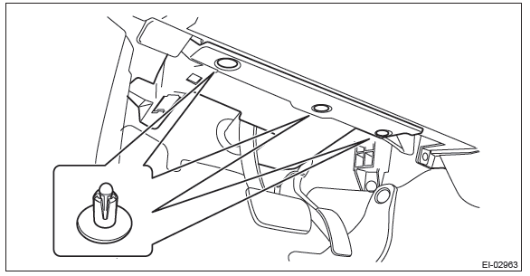
3) Remove the seat heater unit.
2. SEAT HEATER SWITCH
1) Disconnect the ground cable from battery.
2) Remove the console front cover assembly.
- MT model
1. Remove the shift knob.
2. Release the clips and claws, then pull up the console front cover assembly.
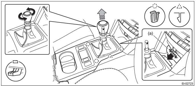
NOTE: Turn over the front center pocket mat (a) and pull up the console front cover from the slit.
3. Disconnect the harness connector and remove the console front cover assembly.
- AT model
1. Remove the select lever knob.
- Lower the cover grip AT.
- Remove the clamp grip pin, then remove the select lever knob.
2. Release the clips and claws, then pull up the console front cover assembly.
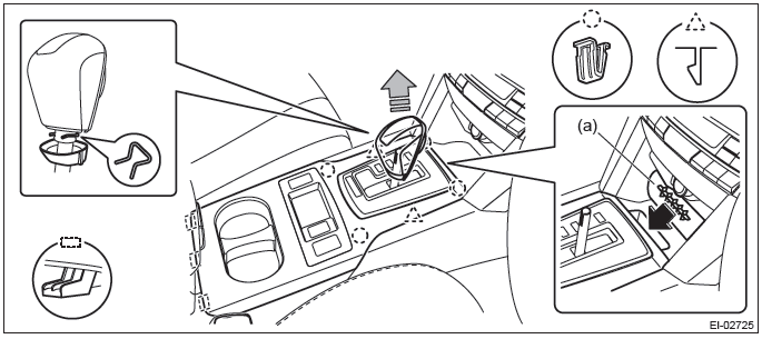
NOTE: Turn over the front center pocket mat (a) and pull up the console front cover from the slit.
3. Disconnect the harness connector and remove the console front cover assembly.
3) Release the claws and remove the seat heater switch from the back of console front cover.
3. SEAT HEATER RELAY AND FUSE
1) Disconnect the ground cable from battery.
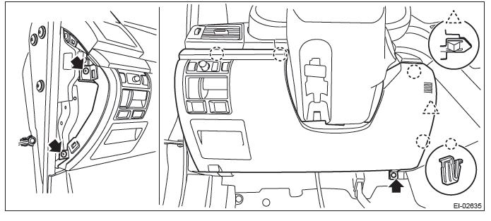
2) Remove the instrument panel lower cover.
- Remove the clips, and remove the instrument panel side cover LH.
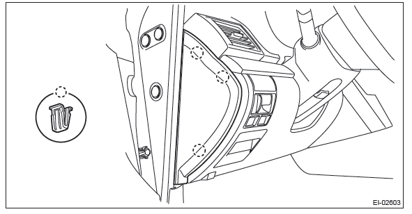
- Remove the clips and data link connector, and remove the instrument panel lower cover under.
- Remove the screws and clips and release the claws, and remove the instrument panel lower cover while disconnecting the harness connectors.
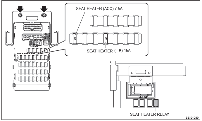
3) Remove the seat heater relay and fuse.
- Remove the joint box bolts.
- Remove the seat heater relay
B: INSTALLATION
Install each part in the reverse order of removal.
C: INSPECTION
1. WIRING DIAGRAM
Refer to "Seat Heater System" in the wiring diagram. <Ref. to WI-234, WIRING DIAGRAM, Seat Heater System.>
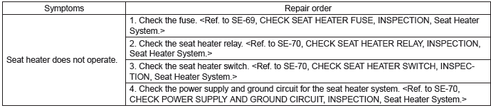
2. DIAGNOSTIC CHART
3. CHECK SEAT HEATER FUSE
Remove the seat heater fuse and inspect visually.
Is the fuse blown out?
- Yes → Replace the fuse.
- No → Check the power supply and ground circuits.
4. CHECK SEAT HEATER RELAY
1) Remove the seat heater relay from the relay holder.
2) Measure the resistance between seat heater relay terminals.
Preparation tool: Circuit tester
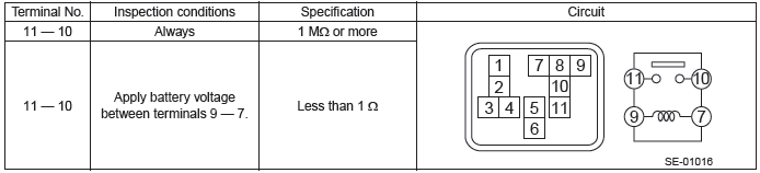
3) Replace the seat heater relay if the inspection result is not within the standard value.
5. CHECK SEAT HEATER SWITCH
1) CHECK SEAT HEATER SWITCH
- Turn the ignition switch to ON.
- Measure the voltage between the seat heater switch and chassis ground when turning the switch to a position other than OFF.
Connector & terminal
LHD side seat
(R42) No. 4 (+) - Chassis ground (-):
RHD side seat
(R45) No. 4 (+) - Chassis ground (-):
Does the voltage fluctuate between 12 V ←→ 0 V?
- Yes → Harness faulty, open circuit of heater or thermostat faulty.
- No → Replace the seat heater switch.
6. CHECK POWER SUPPLY AND GROUND CIRCUIT
1) CHECK POWER SUPPLY CIRCUIT.
- Disconnect the seat heater switch.
- Turn the ignition switch to ON.
- Measure the voltage between harness connector terminal and chassis ground.
Connector & terminal
Driver's seat
(R42) No. 4 (+) - Chassis ground (-):
Passenger's seat
(R45) No. 4 (+) - Chassis ground (-):
Is the voltage 12 V or more?
- Yes → Go to step 2.
- No → Check the harness between the seat heater switch and fuse.
2) CHECK GROUND CIRCUIT.
Measure the resistance between harness connector terminal and chassis ground.
Connector & terminal
Driver seat (manual seat)
(R42) No. 6 - Chassis ground:
(R41) No. 1 - Chassis ground:
Passenger seat (manual seat)
(R45) No. 6 - Chassis ground:
(R44) No. 1 - Chassis ground:
Driver seat (power seat)
(R42) No. 6 - Chassis ground:
(R380) No. 1 - Chassis ground:
Passenger seat (power seat)
(R45) No. 6 - Chassis ground:
(R363) No. 1 - Chassis ground:
Is the resistance less than 10 Ω?
- Yes → The power supply and ground circuits are normal.
- No → Repair the harness.
READ NEXT:
 Security General Description
A: COMPONENT
1. DOOR LOCK ASSEMBLY
Front
Rear
Inner remote ASSY
Front door latch and door lock actuator ASSY
Door outer handle
Door outer handle cover
Key
Relay and Fuse, Door Lock Control System
A: LOCATION
NOTE: For other related fuses, refer to the wiring diagram. <Ref. to WI-15, Power Supply Circuit.>
B: INSPECTION
1. CHECK FUSE.
1) Remove the fuse and inspect visually.
2)
SEE MORE:
Tires and towing
Do not attempt to tow a trailer using the temporary spare tire. The temporary spare tire is not designed to handle the towing load and using it for towing can lead to tire failure or reduced vehicle stability.
Ensure that all tires on your vehicle are properly inflated. Please refer to the "Ti
Antenna
A: REMOVAL
1. RADIO ANTENNA AMPLIFIER
Sedan model
1) Remove the rear quarter trim LH. <Ref. to EI-110, SEDAN MODEL, REMOVAL,
Rear Quarter Trim.>
2) Remove the radio antenna amplifier assembly.
Disconnect the connector.
Remove the bolts, and then remove the radio antenna amplifier assem
