Subaru Outback (BR): Switches and Harness in Manual Transmission
A: REMOVAL
1. BACK-UP LIGHT AND NEUTRAL POSITION SWITCH
1) Disconnect the ground cable from battery.
2) Remove the collector cover. (turbo model)
3) Remove the air intake boot assembly. (non-turbo model) <Ref. to IN(H4SO)-8, REMOVAL, Air Intake Boot.>
4) Remove the intercooler. (turbo model) <Ref. to IN(H4DOTC)-17, REMOVAL, Intercooler.>
5) Disconnect the connector back-up light switch & neutral position switch.
- Non-turbo model
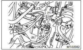
- Neutral position switch connector (Brown)
- Back-up light switch connector (Gray)
- Turbo model
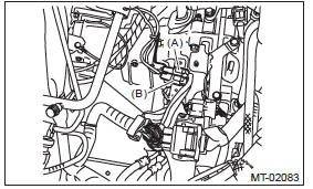
- Neutral position switch connector (Brown)
- Back-up light switch connector (Gray)
6) Lift up the vehicle.
7) Remove the back-up light switch & neutral position switch with the harness.

- Neutral position switch
- Back-up light switch
B: INSTALLATION
1. BACK-UP LIGHT SWITCH & NEUTRAL POSITION SWITCH
1) Install the back-up light switch & neutral position switch with the harness.
NOTE: Use a new gasket.
Tightening torque: 32.3 N*m (3.3 kgf-m, 23.8 ft-lb)
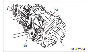
- Neutral position switch
- Back-up light switch
2) Lower the vehicle.
3) Connect the connectors of back-up light switch & neutral position switch.
4) Install the air intake boot assembly. (non-turbo model) <Ref. to IN(H4SO)-8, INSTALLATION, Air Intake Boot.>
5) Install the intercooler. (turbo model) <Ref. to IN(H4DOTC)-18, INSTALLATION, Intercooler.>
6) Install the collector cover. (turbo model)
7) Connect the battery ground terminal.
C: INSPECTION
1. BACK-UP LIGHT SWITCH
Check the back-up light switch. <Ref. to LI-13, INSPECTION, Back-up Light System.>
2. NEUTRAL POSITION SWITCH
1) Turn the ignition switch to OFF.
2) Disconnect the connector of neutral position switch.
3) Measure the resistance between neutral position switch terminals.
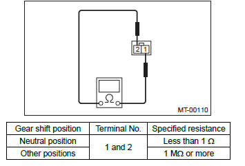
4) Replace faulty parts.
Preparation for Overhaul
A: PROCEDURE
1) Clean oil, grease, dirt and dust from the transmission.
2) When gear oil remains in the transmission, using the TORX bit T70, remove the drain plug, and drain the transmission gear oil completely.
3) Tighten the drain plug using TORX bit T70.
NOTE: Use a new gasket.
Tightening torque:
44 N*m (4.5 kgf-m, 32.5 ft-lb) (Aluminum gasket silver)
70 N*m (7.1 kgf-m, 51.6 ft-lb) (Copper gasket brown)
70 N*m (7.1 kgf-m, 51.6 ft-lb) (Metal gasket black)
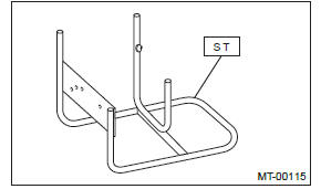
4) Attach the transmission to the ST.
ST 499937100 TRANSMISSION STAND
5) Apply oil to rotating parts before assembly.
6) All disassembled parts, if to be reused, should be reinstalled in the original positions and directions.
7) Gaskets, lock washers and lock nuts must be replaced with new ones.
8) Apply liquid gasket to the specified areas to prevent leakage.
READ NEXT:
 Transfer Case and Extension
Case Assembly
Transfer Case and Extension
Case Assembly
A: REMOVAL
1) Remove the manual transmission assembly
from the vehicle. <Ref. to 6MT-25, REMOVAL,
Manual Transmission Assembly.>
2) Remove the back-up light switch and the neutral
position swit
Shift Link Assembly
A: REMOVAL
1) Remove the manual transmission assembly
from the vehicle. <Ref. to 6MT-25, REMOVAL,
Manual Transmission Assembly.>
2) Remove the back-up light switch and the neutral
position swit
Main Shaft Assembly for Single-Range
A: REMOVAL
1) Remove the manual transmission assembly
from the vehicle. <Ref. to 6MT-25, REMOVAL,
Manual Transmission Assembly.>
2) Remove the transfer case together with the extension
case ass
SEE MORE:
Roll Connector
A: REMOVAL
1) Position the front wheels straight ahead. (After moving a vehicle 5 m (16
ft) or more with front wheels positioned
straight ahead, make sure that the vehicle moves straight ahead.)
2) Turn the ignition switch to OFF.
3) Disconnect the ground cable from battery and wait for at least 6
Door open warning light
When the ignition switch is in the “ON” position, the door open warning light
illuminates for approximately 2 seconds and then turns off.
The door open warning light illuminates if any door, the rear gate (Outback)
or trunk lid (Legacy) is not fully closed. This function is effective even
