Subaru Outback (BR): Air Conditioning System
A: WIRING DIAGRAM
Refer to "Air Conditioning System" in the wiring diagram. <Ref. to WI-53, WIRING DIAGRAM, Air Conditioning System.>
B: ELECTRICAL SPECIFICATION
Refer to "Auto A/C Control Module I/O Signal" of "HVAC SYSTEM (DIAGNOSTICS)" section. <Ref. to AC(diag)- 6, ELECTRICAL SPECIFICATION, Control Module I/O Signal.>
C: INSPECTION
Refer to "Basic Diagnostic Procedure" of "HVAC SYSTEM (DIAGNOSTICS)" section. <Ref. to AC(diag)-2, Basic Diagnostic Procedure.>
D: NOTE
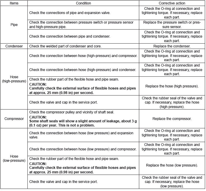
For procedure of each component in the air conditioning system, refer to the respective section.
- Blower motor unit assembly: <Ref. to AC-32, Blower Motor Unit Assembly.>
- Blower motor: <Ref. to AC-36, Blower Motor.>
- Power transistor (auto A/C model): <Ref. to AC-38, Power Transistor (Auto A/C Model).>
- Blower resistor (manual A/C model): <Ref. to AC-39, Blower Resistor (Manual A/C Model).>
- Control panel: <Ref. to AC-46, Control Panel.>
- Control module: <Ref. to AC-54, Control Unit.>
- Compressor: <Ref. to AC-55, Compressor.>
- Condenser: <Ref. to AC-58, Condenser.>
- Heater and cooling unit: <Ref. to AC-62, Heater and Cooling Unit.>
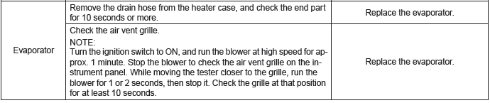
- Evaporator: <Ref. to AC-66, Evaporator.>
- Expansion valve: <Ref. to AC-74, Expansion Valve.>
- Hose & pipe: <Ref. to AC-76, Hose and Pipe.>
- Ambient sensor (auto A/C model): <Ref. to AC-78, Ambient Sensor (Auto A/C Model).>
- Sunload sensor (auto A/C model): <Ref. to AC-80, Sunload Sensor (Auto A/C Model).>
- In-vehicle sensor (auto A/C model): <Ref. to AC-82, In-Vehicle Sensor (Auto A/C Model).>
- Evaporator sensor: <Ref. to AC-87, Evaporator Sensor.>
- Intake door actuator: <Ref. to AC-90, FRESH/RECIRC Door Actuator.>
- Mode door actuator: <Ref. to AC-92, Mode Door Actuator.>
- Air mix door actuator: <Ref. to AC-95, Air Mix Door Actuator.>
Refrigerant Pressure with Manifold Gauge Set
A: PROCEDURE
1. CHECK REFRIGERANT GAS PRESSURE
Preparation tool:
Manifold gauge set
Thermometer
1) Prepare the vehicle.
NOTE: Check that the ambient temperature is 25 - 40ºC (77 - 104ºF) and that the humidity is 30% - 80%.
- Place the vehicle in the shade and windless condition, and open the front hood.
- Open the front windows and close all doors.
2) Connect the manifold gauge set, and then check the refrigerant pressure.
- Connect the manifold gauge set, and start the engine.
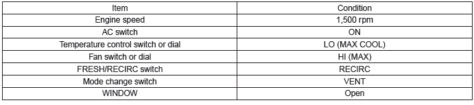
- Set the vehicle to the following conditions.
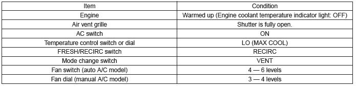
- In the condition of step (2), idle the engine for 30 minutes.
- Read the gauge values on both high pressure side and low pressure side for manifold gauge.
3) Measure the air vent grille outlet opening temperature, ambient temperature and humidity.
NOTE: For outlet opening temperature, measure the average temperature of center grille assembly and side grille assembly.
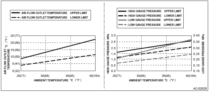
4) Check that the high and low pressures and outlet opening temperature for ambient temperature and humidity is within the standard value described in the chart below.
5) Refer to "DIAGNOSIS WITH SYMPTOM" if the inspection result is not within the standard value. <Ref. to AC-21, INSPECTION WITH PRESSURE SYMPTOM, INSPECTION, Refrigerant Pressure with Manifold Gauge Set.>
B: INSPECTION
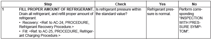
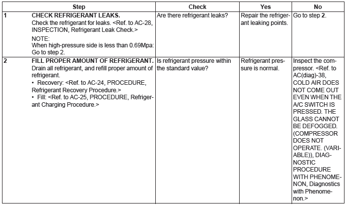
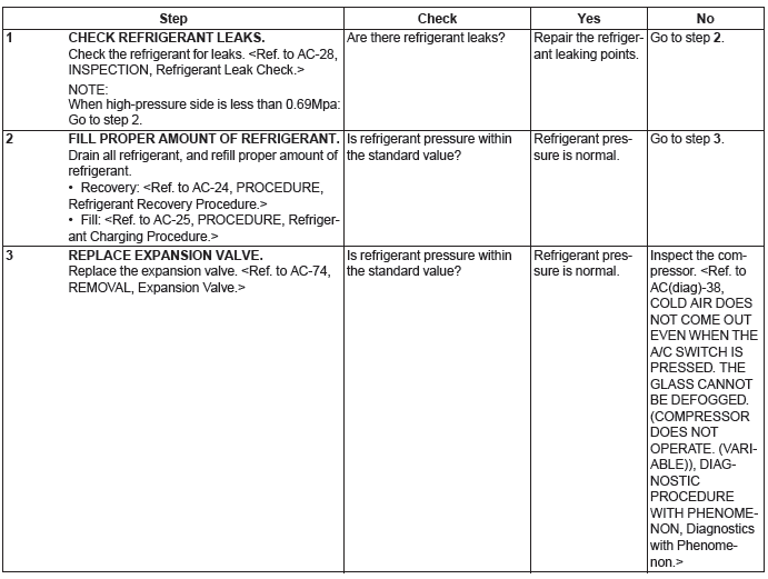
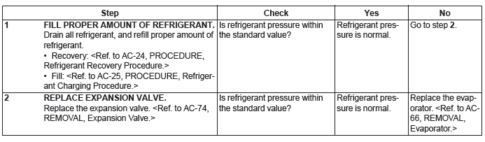
1. INSPECTION WITH PRESSURE SYMPTOM
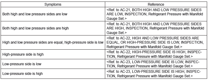
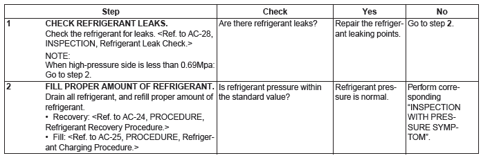
2. BOTH HIGH AND LOW PRESSURE SIDES ARE LOW
3. BOTH HIGH AND LOW PRESSURE SIDES ARE HIGH
4. HIGH AND LOW PRESSURE SIDES ARE EQUAL, OR HIGH-PRESSURE SIDE IS LOW
5. HIGH-PRESSURE SIDE IS HIGH

6. LOW-PRESSURE SIDE IS LOW
7. LOW-PRESSURE SIDE IS HIGH
Refrigerant Recovery Procedure
A: PROCEDURE
Preparation tool:
Manifold gauge set
Refrigerant recovery system
CAUTION:
- During operation, be sure to wear protective goggles and protective gloves.
- Connect the refrigerant recovery system with the manifold gauge set to discharge the refrigerant from the A/C system and recycle the gas.
- When recycling the discharged refrigerant, keep service cans on hand. Because the recovery rate with the recovery system is approx. 90%, service cans are necessary to charge the refrigerant.
- Follow the detailed operation procedure described in the operation manual attached to the refrigerant recovery system.
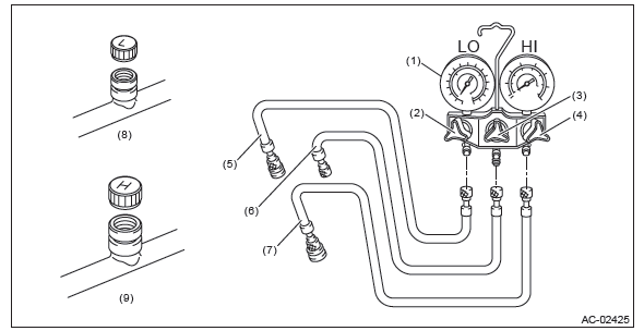
- Manifold gauge
- Low pressure valve
- Center valve
- High pressure valve
- Low-pressure hose
- Center manifold hose (vacuum pump and refill)
- High-pressure hose
- Low-pressure side service port
- High-pressure side service port
1) Perform compressor oil return operation. <Ref. to AC-31, PROCEDURE, Compressor Oil.>
2) Stop the engine.
3) Attach the manifold gauge set.
- Check that all valves are fully closed.
- Install the low/high pressure hoses to the service ports on the low/high pressure sides of the vehicle respectively.
CAUTION: Confirm that the connections are secure.
- Connect the center hose to the refrigerant recovery system.
4) Follow the operation manual attached to the refrigerant recovery system to collect the refrigerant.
Refrigerant Charging Procedure
A: PROCEDURE
Preparation tool:
Manifold gauge set
Vacuum pump
Can tap
Weight scale
CAUTION:
- While working, be sure to wear protective goggles and protective gloves.
- Air in the cycle can cause insufficient air conditioning, and water in the cycle can cause clogging in the cycle (icing) and rust. To remove this air and water content, use a vacuum pump to perform evacuation before filling with refrigerant. By making the inside of the cycle a vacuum, the water content will evaporate even at normal temperatures, and can be removed.
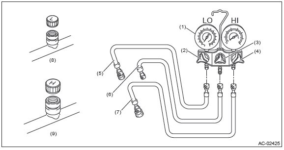
- Manifold gauge
- Low pressure valve
- Center valve
- High pressure valve
- Low-pressure hose
- Center manifold hose (vacuum pump and refill)
- High-pressure hose
- Low-pressure side service port
- High-pressure side service port
1) Attach the manifold gauge set.
- Check that all valves are fully closed.
- Install the low/high pressure hoses to the service ports on the low/high pressure sides of the vehicle respectively.
CAUTION: Confirm that the connections are secure.
- Connect the center manifold hose of the manifold gauge to the vacuum pump.
2) Perform evacuation.
CAUTION:
Make sure to perform evacuation using a vacuum pump.
- Open the low-pressure valve, high-pressure valve and center valve.
- Operate the vacuum pump.
- Perform evacuation for 5 minutes or more, and when the low pressure gauge needle reaches -0.1 MPa (1.0 kgf/cm2, 14 psi), close the center manifold hose valve, and stop the vacuum pump.
- Leave alone for 5 to 10 minutes after closing the low pressure side and high pressure side valves, and check whether there is any change in the low pressure gauge needle indication. If the needle position changes, this indicates a leak. Check the pipe and hose connections, and repair the location with the problem. In this case, repeat again from step 1).
- If there is no leakage, continue evacuation for additional 20 - 30 minutes, close all valves and then stop the vacuum pump.
3) Charge refrigerant.
- Follow the can tap operation manual, install to the refrigerant can.
- Disconnect the center manifold hose from the vacuum pump, and connect the hose to the tap valve.
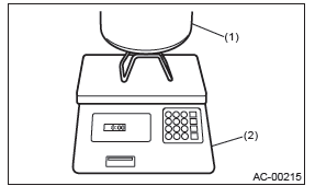
NOTE: When a 13.6 kg (30 lb) refrigerant container (1) is used, measure the amount of refrigerant with a refrigerant charging scale (2), and connect with the center manifold hose.
- Open the tap valve of HFC-134a supply container (refrigerant can or refrigerant container).
- Loosen the center manifold hose connection on the manifold gauge for a few seconds (if there is a purge valve on the manifold gauge, push this instead) to allow the air in the center manifold hose to be bled by the refrigerant pressure.
- Open the low-pressure side and high-pressure side valves of the manifold gauge to fill with refrigerant.
NOTE: If the HFC-134a supply container is empty, close all valves of manifold gauge and tap valve of HFC-134a supply container, and replace the empty container. After replacing with a new HFC-134a supply container, perform air purge, and resume the filling operation.
- If the low pressure gauge indicates approximately 0.2 MPa (2.0 kgf/cm2, 29 psi) or refrigerant filling efficiency drops, close the low-pressure side valve and high-pressure side valve.
- Check that the low-pressure side valve and high-pressure side valve are closed, turn off the A/C switch and start the engine.
CAUTION: When filling with the engine running, do not open the high pressure side valve. Always fill from the low pressure side.
- To prevent damage to the compressor, push the A/C switch ON-OFF quickly a few times.
- Set the vehicle to the following conditions.
- Open the low-pressure side valve, check the refrigerant pressure with a manifold gauge and fill with refrigerant up to the specified amount. <Ref. to AC-21, INSPECTION WITH PRESSURE SYMPTOM, INSPECTION, Refrigerant Pressure with Manifold Gauge Set.>
4) Using an electronic leak detector (leak tester), check for refrigerant leaks in the system. <Ref. to AC-28, INSPECTION, Refrigerant Leak Check.>
5) After filling with refrigerant, close all valves and remove the manifold gauge set.
6) Attach cap to the service port of the low-pressure side and high-pressure side.
Refrigerant Leak Check
A: INSPECTION
Preparation tool:
Manifold gauge set
Electronic leak detector (leak tester)
1) Attach the manifold gauge set.
- Check that all valves are fully closed.
- Install the low/high pressure hoses to the service ports on the low/high pressure sides of the vehicle respectively.
CAUTION: Confirm that the connections are secure.
- Start the engine, operate the A/C system for approx. 10 minutes, and check that the high-pressure side indicates 0.69 MPa (7.0 kgf/cm2, 100 psi) or more.
2) Stop the engine to start the leak test.
READ NEXT:
 Relay and Fuse, check fuse
A: LOCATION
NOTE: For other related fuses, refer to the wiring diagram. <Ref. to WI-15, Power Supply Circuit.>
B: INSPECTION
1. CHECK FUSE.
1) Remove the fuse and inspect visually.
2) If
Heater Core
A: REMOVAL
1) Disconnect the ground cable from battery.
2) Using the refrigerant recovery system, discharge refrigerant. <Ref. to AC-24,
PROCEDURE, Refrigerant
Recovery Procedure.>
3) Drain t
HVAC System Control Panel
A: REMOVAL
1. AUTO A/C MODEL
1) Disconnect the ground cable from battery.
2) Remove the center panel assembly.
CAUTION: Do not put your finger on the fin of the air vent grille. Doing so may damag
SEE MORE:
Drive Pinion Shaft Assembly in Manual Transmission
A: REMOVAL
1) Remove the manual transmission assembly from the vehicle. <Ref. to 6MT-25, REMOVAL, Manual Transmission Assembly.>
2) Remove the transfer case together with the extension case assembly. <Ref. to 6MT-40, REMOVAL, Transfer Case and Extension Case Assembly.>
3) Remove the t
General Description of Airbag System
A: COMPONENT
Front sub sensor RH
Front sub sensor LH
Airbag warning light (in combination meter)
Airbag module ASSY (driver)
Airbag module ASSY (passenger)
Airbag control module
Steering roll connector
Curtain airbag sensor LH
Curtain airbag mo
