Subaru Outback (BR): Air Breather Hose
A: REMOVAL
1) Remove the air intake boot assembly. <Ref. to IN(H4SO)-8, REMOVAL, Air Intake Boot.>
2) Remove the two air breather hoses.
3) Remove the oil cap.
B: INSTALLATION
Install in the reverse order of removal.
NOTE: Use new O-rings.
C: INSPECTION
- Check the hose for peeling, crack or clogging.
- Check the oil cap is not cracked or clogged.
- Check O-ring of oil cap is not damaged.
Drive Plate
A: REMOVAL
1) Remove the transmission assembly from the vehicle. <Ref. to CVT-55, REMOVAL, Automatic Transmission Assembly.>
2) Set the ST.
ST 498497100 CRANKSHAFT STOPPER
3) Remove the drive plate and reinforcement drive plate.
B: INSTALLATION
1) Temporarily install the drive plate and reinforcement drive plate.
2) Set the ST.
ST 498497100 CRANKSHAFT STOPPER
3) Tighten the drive plate mounting bolt in three stages.
NOTE: Fix the engine unit.
- Tighten the drive plate mounting bolt.
Tightening torque: 10 N*m (1.0 kgf-m, 7.4 ft-lb)
- Additionally tighten the drive plate mounting bolts.
Tightening torque: 40 N*m (4.1 kgf-m, 29.5 ft-lb)
- While checking the tightening angle with the ST, tighten the drive plate mounting bolts to the specified angle.
Tightening angle: 30º+-5º
ST 18854AA000 ANGLE GAUGE
4) Install the transmission assembly to the vehicle. <Ref. to CVT-70, INSTALLATION, Automatic Transmission Assembly.>
C: INSPECTION
Check the drive cable for damage.
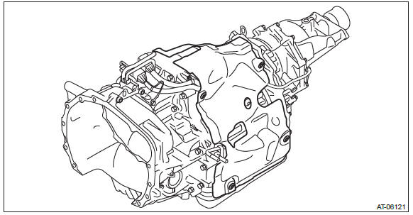
Preparation for Overhaul
A: GENERAL DESCRIPTION
Before disassembling and assembling the transmission, follow the following procedures to prepare.
B: PROCEDURE
1) Clean the transmission exterior.
2) Remove the torque converter assembly. <Ref. to CVT-136, Torque Converter Assembly.>
3) Attach the ST on the transmission.
ST 18632AA000 STAND ASSY
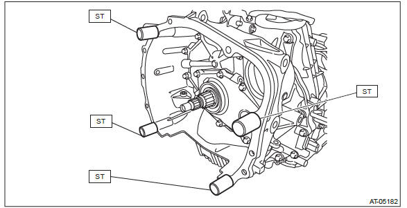
4) Remove the transmission cover on the transmission upper side.
NOTE: Install using the following tightening torque.
Tightening torque: 8 N*m (0.8 kgf-m, 5.9 ft-lb)
5) Place the transmission assembly on end.
Torque Converter Assembly
A: REMOVAL
1) Remove the transmission assembly from the vehicle. <Ref. to CVT-55, REMOVAL, Automatic Transmission Assembly.>
2) Pull out the torque converter assembly horizontally.
CAUTION: Do not scratch the inside of engaging parts.
3) Remove the O-ring from the front reduction drive gear.
B: INSTALLATION
1) Install the O-ring to front reduction drive gear.
NOTE:
- Use new O-rings.
- Apply CVTF to the O-ring.
2) While holding the torque converter assembly by hand, carefully install it into the torque converter case.
NOTE:
- Apply CVTF to the oil seal lip.
- Do not damage the oil seal and O-ring.
3) Engage the splines while gently rotating the torque converter assembly by hand, and securely insert the assembly.
4) Measure depth "A", from converter case end surface to drive plate contacting surface.
Standard (A) (reference): 6.8 mm (0.268 in)
5) Install the transmission assembly to the vehicle. <Ref. to CVT-70, INSTALLATION, Automatic Transmission Assembly.>
C: INSPECTION
- Check the protrusion of torque converter center (front boss) is not deformed or damaged.
- Check the ring gear and exterior for break or damage.
Extension Case
A: REMOVAL
1) Remove the transmission assembly from vehicle body. <Ref. to CVT-55, REMOVAL, Automatic Transmission Assembly.>
2) Remove the front wheel speed sensor. <Ref. to CVT-107, REMOVAL, Front Wheel Speed Sensor.>
3) Remove the harness clip, and remove the extension case.
NOTE: The total number of extension case mounting bolts is ten.
B: INSTALLATION
1) Clean the mating surface of the extension case and intermediate case.
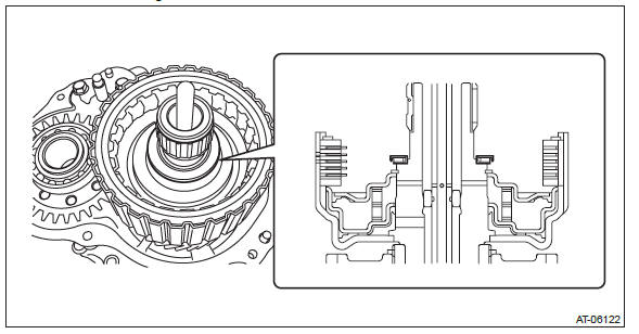
2) Select the thrust needle bearing. <Ref. to CVT-143, ADJUSTMENT, Rear Drive Shaft.>
3) Select the shim for transfer reduction driven gear. <Ref. to CVT-161, ADJUSTMENT, Transfer Reduction Driven Gear.>
4) Install the selected thrust needle bearing to transfer clutch assembly.
NOTE: Install the thrust needle bearing in the correct direction.
5) Attach the selected shim to transfer reduction driven gear assembly.
6) Apply liquid gasket to extension case seamlessly.
Liquid gasket: THREE BOND 1215 (Part No. 004403007) or equivalent
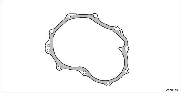
7) Install the extension case.
Tightening torque: 25 N*m (2.5 kgf-m, 18.4 ft-lb)
8) Install the front wheel speed sensor. <Ref. to CVT-107, INSTALLATION, Front Wheel Speed Sensor.>
9) Install the transmission assembly. <Ref. to CVT-70, INSTALLATION, Automatic Transmission Assembly.>
C: DISASSEMBLY
1) Remove the dust cover from extension case.
2) Remove the extension case oil seal from the extension case.
D: ASSEMBLY
1) Press-fit the dust cover into extension case.
2) Install the extension case oil seal to extension case.
ST 498057300 INSTALLER
E: INSPECTION
- Check there is no leak of CVTF from the joint between extension case and intermediate case.
- Check there is no damage or cracks on the extension case.
F: ADJUSTMENT
NOTE: When replacing the extension case, select the shims for rear drive shaft thrust needle bearing and transfer reduction driven gear. <Ref. to CVT-143, ADJUSTMENT, Rear Drive Shaft.> <Ref. to CVT-161, ADJUSTMENT, Transfer Reduction Driven Gear.>
Rear Drive Shaft
A: REMOVAL
1) Remove the transmission assembly from vehicle body. <Ref. to CVT-55, REMOVAL, Automatic Transmission Assembly.>
2) Remove the extension case. <Ref. to CVT-138, REMOVAL, Extension Case.>
3) Remove the rear drive shaft.
B: INSTALLATION
1) Select the thrust needle bearing. <Ref. to CVT-143, ADJUSTMENT, Rear Drive Shaft.>
2) Install the selected thrust needle bearing to transfer clutch assembly.
NOTE: Install the thrust needle bearing in the correct direction.
3) Install the rear drive shaft.
4) Install the extension case. <Ref. to CVT-138, INSTALLATION, Extension Case.>
5) Install the transmission assembly to the vehicle. <Ref. to CVT-70, INSTALLATION, Automatic Transmission Assembly.>
C: DISASSEMBLY
1) Remove the ball bearing using ST.
ST 498077600 REMOVER
D: ASSEMBLY
1) Using the ST, install the ball bearing.
NOTE:
- Use a new ball bearing.
- Apply CVTF to press-fitting surface of ball bearing.
ST 399513600 INSTALLER
E: INSPECTION
- Check each part for crack, damage or dust.
- Check the ball bearing for smooth rotation.
- Check the ball bearing for excessive looseness.
F: ADJUSTMENT
NOTE: When replacing the rear drive shaft or bearing, select the thrust needle bearing.
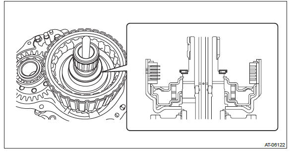
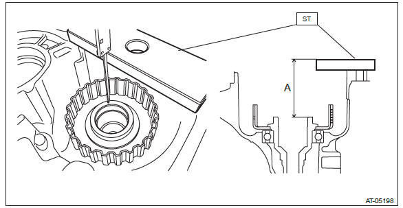
1) Using the ST, measure the distance "A" from ST end face to rear drive shaft thrust needle bearing catch surface.
ST 398643600 GAUGE
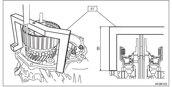
2) Using the ST, measure the height "B" from the intermediate case mating surface to the ST end face.
NOTE: Place the measurement tool at the dent on ST upper side to measure.
ST 499737100 PULLER SET
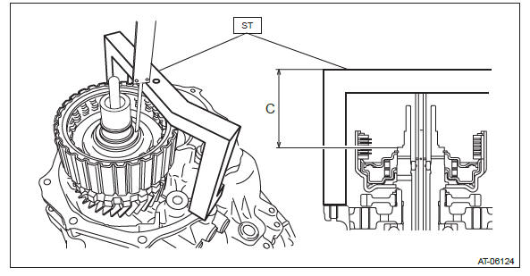
3) Using the ST, measure the height "C" from ST end face to transfer clutch assembly thrust needle bearing catch surface.
NOTE: Place the measurement tool at the dent on ST upper side to measure.
ST 499737100 PULLER SET
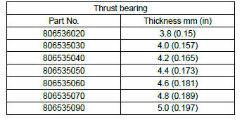
4) Obtain the thickness of thrust bearing using the following formula to select the thrust bearing.
T mm = (A - 15) - (B - C) - (0.05 - 0.25)
[T in = (A - 0.59) - (B - C) - (0.002 - 0.01) ]
T: Thrust bearing thickness
A: Height from the ST end face to the rear drive shaft thrust needle bearing
catch surface
B: Height from the mating surface of the intermediate case to the ST end face
C: Height from the ST end face to the transfer clutch assembly thrust needle
bearing catch surface
15 mm (0.591 in): Thickness of ST
0.05 - 0.25 mm (0.002 - 0.01 in): Clearance
READ NEXT:
 Transfer Clutch
A: REMOVAL
1) Remove the transmission assembly from the vehicle. <Ref. to CVT-55,
REMOVAL, Automatic Transmission
Assembly.>
2) Remove the extension case. <Ref. to CVT-138, REMOVAL, Extensi
Transfer Reduction Driven Gear
A: REMOVAL
1) Remove the transmission assembly from the vehicle. <Ref. to CVT-55,
REMOVAL, Automatic Transmission
Assembly.>
2) Remove the extension case. <Ref. to CVT-138, REMOVAL, Extensio
Intermediate Case
A: REMOVAL
1) Remove the transmission assembly from vehicle body. <Ref. to CVT-55,
REMOVAL, Automatic Transmission
Assembly.>
2) Remove the extension case. <Ref. to CVT-138, REMOVAL, Extens
SEE MORE:
Front Bumper
A: REMOVAL
1) Disconnect the ground cable from battery.
2) Remove the front bumper face assembly.
Remove the clips, turn over the front mud guard, and disconnect the fog
light connector. (Model with
fog light)
Remove the clips at the upper side of the bumper.
Remove the clips from the fen
Warranties and maintenance
vehicle damage or malfunction caused by trailer towing. If you use your vehicle
to tow a trailer, more frequent maintenance will be required due to the additional
load. (Refer to “Maintenance schedule under severe driving conditions” in the “Warranty
and Maintenance Booklet”.)
Under n
