Subaru Outback (BR): Transfer Clutch
A: REMOVAL
1) Remove the transmission assembly from the vehicle. <Ref. to CVT-55, REMOVAL, Automatic Transmission Assembly.>
2) Remove the extension case. <Ref. to CVT-138, REMOVAL, Extension Case.>
3) Remove the rear drive shaft. <Ref. to CVT-141, REMOVAL, Rear Drive Shaft.>
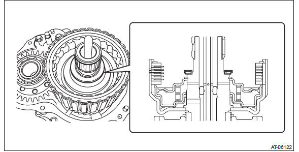
4) Remove the thrust needle bearing and needle bearing.
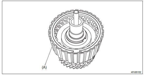
5) Remove the transfer clutch assembly.
6) Remove the seal ring from transfer clutch assembly.
B: INSTALLATION
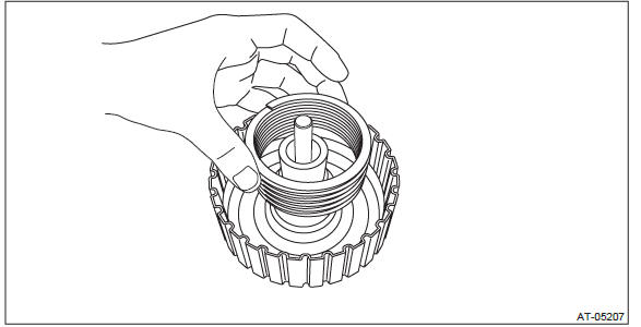
1) Apply vaseline to the seal ring and attach it to the seal ring groove of transfer clutch assembly.
NOTE:
- Use a new seal ring.
- When installing the seal ring, do not expand the seal ring too much.
2) Install the transfer clutch assembly.
3) Select the thrust needle bearing. <Ref. to CVT-143, ADJUSTMENT, Rear Drive Shaft.>
4) Install the selected thrust needle bearing and needle bearing to transfer clutch assembly.
NOTE: Install the thrust needle bearing in the correct direction.
5) Install the rear drive shaft. <Ref. to CVT-141, INSTALLATION, Rear Drive Shaft.>
6) Install the extension case. <Ref. to CVT-138, INSTALLATION, Extension Case.>
7) Install the transmission assembly to the vehicle. <Ref. to CVT-70, INSTALLATION, Automatic Transmission Assembly.>
C: DISASSEMBLY
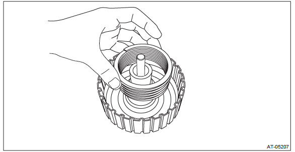
1) Remove the snap ring, and then remove the retaining plate, drive plate and driven plate.
- Snap ring
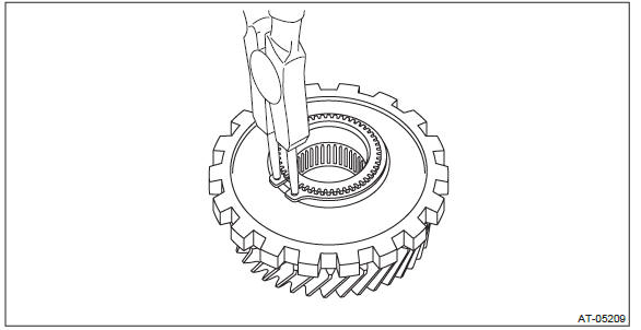
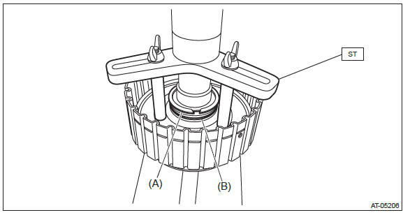
2) Using the ST, remove the snap ring.
ST 18762AA000 COMPRESSOR SPECIAL TOOL

- Snap ring
- Transfer clutch piston seal
3) Remove the transfer clutch piston seal.
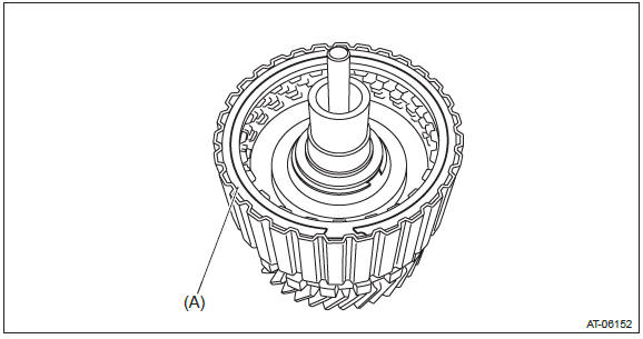
4) Remove the return spring.
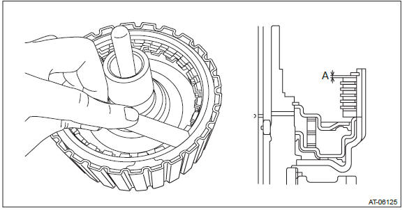
5) Remove the transfer clutch piston by blowing compressed air through transfer clutch assembly hole.
NOTE: Block the hole opposite to the one to be blown with compressed air by your finger.
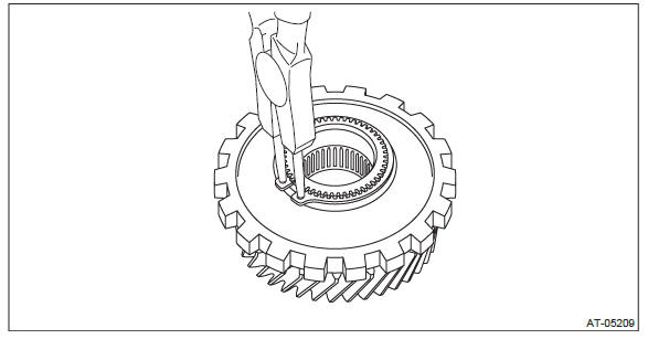
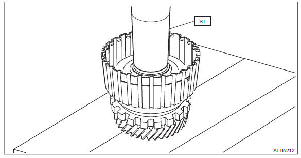
6) Using ST, remove transfer drive gear, parking gear and ball bearing.
ST 18767AA000 BEARING REMOVER NOTE: Let the ST sit on the parking gear.
7) Remove the snap ring from transfer reduction drive gear.
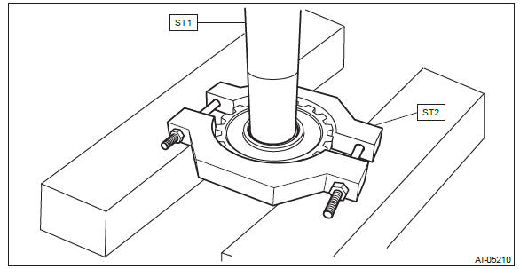
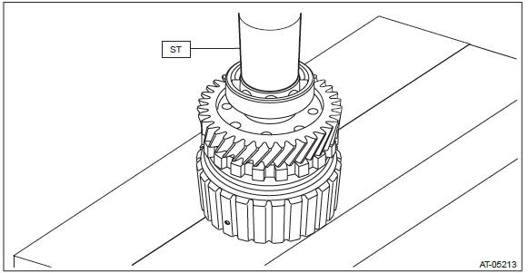
8) Using the ST, remove the parking gear from transfer reduction drive gear.
ST1 499277100 BUSHING 1-2 INSTALLER
ST2 18767AA000 BEARING REMOVER
D: ASSEMBLY
1) Using the ST, install the parking gear to transfer reduction drive gear.
ST 398177700 INSTALLER
2) Install the snap ring to transfer reduction drive gear.
3) Using the ST, install the transfer reduction drive gear to transfer reduction drive gear shaft.
ST 499277100 BUSHING 1-2 INSTALLER
4) Using the ST, install the ball bearing.
NOTE: Use a new ball bearing.
ST 499277100 BUSHING 1-2 INSTALLER
5) Attach the transfer clutch piston to the reduction drive gear shaft.
NOTE: Apply CVTF to the transfer clutch piston lip.
6) Install the return spring.
7) Install the transfer clutch piston seal.
8) Using the ST, install the snap ring.
ST 18762AA000 COMPRESSOR SPECIAL TOOL
- Snap ring
- Transfer clutch piston seal
9) Install the pressure plate, driven plate, drive plate and snap ring.
- Snap ring
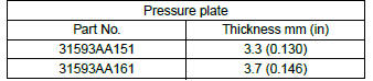
10) Before measuring clearance "A", place same thickness shims on both sides to prevent the retaining plate from tilting.
11) When clearance "A" exceeds the limit for use, replace the drive plate and driven plate as a set, and select and adjust the pressure plate within the initial specified value.
Initial standard: 0.7 - 1.1 mm (0.028 - 0.043 in)
Limit thickness: 1.6 mm (0.063 in)
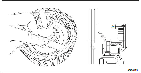
12) Check the clearance between the snap ring and retaining plate. <Ref. to CVT-156, INSPECTION, Transfer Clutch.>
E: INSPECTION
- Inspect the drive plate facing for wear and damage.
- Driven plate for discoloration (burned color)
- Make sure the snap ring is not worn and the return spring has no permanent distortion, damage, or deformation.
- Check the lip seal for damage.
- Inspect the extension end play, and adjust it to within the standard value. <Ref. to CVT-157, ADJUSTMENT, Transfer Clutch.>
1) Before measuring clearance "A" between snap ring and retaining plate, place same thickness shims on both sides to prevent the retaining plate from tilting.
2) When clearance "A" exceeds the limit for use, replace the drive plate and driven plate as a set, and select the pressure plate within the initial specified value.
Initial standard: 0.7 - 1.1 mm (0.028 - 0.043 in)
Limit thickness: 1.6 mm (0.063 in)
3) Check for tight corner braking phenomenon when the vehicle is moved forward with the steering fully turned. If tight corner braking occurs, perform the following procedures.
- With the steering wheel held at fully turned position, drive the vehicle in "D" range and with vehicle speed at approx. 5 km/h (3 MPH) in both clockwise and counterclockwise directions for approx. ten times each, while repeating acceleration and braking intermittently.
- If the tight corner braking phenomenon still persists, drive the vehicle again in a circle for several laps.
F: ADJUSTMENT
NOTE: Refer to the Rear Drive Shaft. <Ref. to CVT-143, ADJUSTMENT, Rear Drive Shaft.>
READ NEXT:
 Transfer Reduction Driven Gear
A: REMOVAL
1) Remove the transmission assembly from the vehicle. <Ref. to CVT-55,
REMOVAL, Automatic Transmission
Assembly.>
2) Remove the extension case. <Ref. to CVT-138, REMOVAL, Extensio
Intermediate Case
A: REMOVAL
1) Remove the transmission assembly from vehicle body. <Ref. to CVT-55,
REMOVAL, Automatic Transmission
Assembly.>
2) Remove the extension case. <Ref. to CVT-138, REMOVAL, Extens
Reverse Brake Assembly
A: REMOVAL
NOTE:
For removal of reverse brake assembly, refer to "Intermediate Case". <Ref. to
CVT-165, REMOVAL, Intermediate
Case.>
B: INSTALLATION
NOTE:
For removal of reverse brake assembly,
SEE MORE:
Select Cable
A: REMOVAL
1) Shift the select lever to "N" range.
2) Disconnect the ground cable from battery.
3) Lift up the vehicle.
4) Remove the front exhaust pipe and rear exhaust pipe.
2.5 L model
<Ref. to EX(H4SO)-5, REMOVAL, Front Exhaust Pipe.> <Ref. to EX(H4SO)-9,
REMOVAL, Rear Exhaust
Turbo models
1) Air intake duct 2) Air cleaner case 3) Clamp
1. Remove the hydraulic hose in the power steering system from the clip on the
air intake duct.
2. Remove the hydraulic hose from the clip on the right side of the air cleaner
case.
3. Unsnap the two clamps holding the air cleaner case cover.
