Subaru Outback (BR): Universal Joint
A: REMOVAL
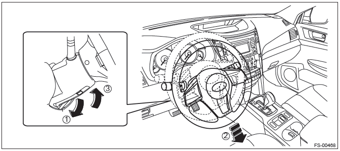
1) Adjust the tilt position of the steering column to the lowest position and lock the tilt lever.
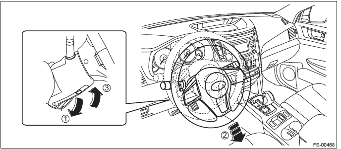
2) Prevent the steering wheel from turning using the seat belt.
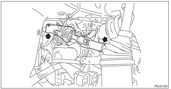
3) Remove the universal joint.
- Place alignment marks on universal joint.
- Remove the universal joint bolt and remove the universal joint.
B: INSTALLATION
1) Before installation, check the universal joint. <Ref. to PS-23, INSPECTION, Universal Joint.>
2) Adjust the tilt position of the steering column to the lowest position and lock the tilt lever.
3) Align the cutout portion (a) at serrated section of the column shaft (c) and yoke (b), then install the universal joint into column shaft.
CAUTION: Be sure to align the protrusion section (a) of the column shaft side with the cutout (a) of the serration.
If the protrusion is aligned with the other cutout (d), the universal joint bolt cannot be assembled.
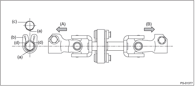
- Column shaft side
- Gearbox side
4) Install the universal joint to the serrations of gearbox assembly by matching alignment marks.
5) Tighten the bolts on the gearbox side first, and then the column shaft side.
CAUTION: Be sure to follow the tightening order and tightening torque of universal joint to avoid the steering effort from becoming heavy.
Tightening torque: 24 N*m (2.45 kgf-m, 17.7 ft-lb)
Clearance between universal joint coupling and adjacent parts: 15 mm (0.59 in) or more
C: INSPECTION
Check for wear, damage or any other faults.
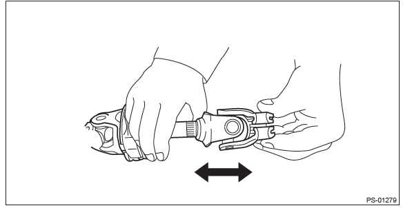
1) Check the universal joint for excessive looseness.
Service limit: Universal joint play: 0 mm (0 in)
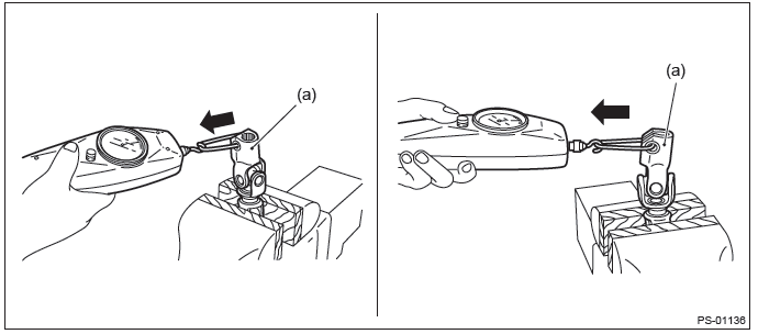
2) Measure the swing torque of universal joint.
- Place the universal joint between wooden blocks and fix it on a vise.
- With the yoke (a) of gearbox side facing up, measure the swing torque in two directions.
- With the yoke (b) of steering column side facing up, measure the swing torque in two directions.
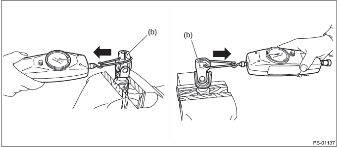
Service limit: Maximum load: 7.3 N (0.74 kgf, 1.64 lbf) or less
- Replace as necessary, if it is found defective.
READ NEXT:
 Steering Column
A: REMOVAL
1) Adjust the tilt position to the lowest position and lock the tilt lever.
2) Remove the driver's airbag module assembly.
Push in the snap pin using a hexagon wrench or equivalent wrapp
Steering Gearbox
A: REMOVAL
1) Remove the cradle. <Ref. to FS-20, REMOVAL, Cradle.>
2) Remove the bolts, and remove left and right main mounting brackets.
3) Remove the bolts and remove the steering gearbox.
C
Power Steering Oil Pump
A: REMOVAL
1) Disconnect the ground cable from battery.
2) Remove the V-belts. <Ref. to ME(H4SO)-43, REMOVAL, V-belt.>
3) Remove the power steering oil pump assembly.
Disconnect the co
SEE MORE:
Wheel Alignment (inspection, adjustment)
A: INSPECTION
Check the following items before performing the wheel alignment measurement.
Tire inflation pressure
Uneven wear of RH and LH tires, or difference of sizes
Tire runout
Excessive play and wear of ball joint
Excessive play and wear of tie-rod end
Excessiv
Changing the oil and oil filter
Change the oil and oil filter according to the maintenance schedule in the “Warranty
and Maintenance Booklet”.
The engine oil and oil filter must be changed more frequently than listed in
the maintenance schedule when driving on dusty roads, when short trips are frequently
made, or when d
