Subaru Outback (BR): ATF Cooler Pipe and Hose
A: REMOVAL
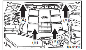
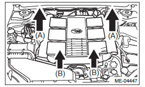
1) Remove the collector cover.
NOTE: Follow the steps below when removing the collector cover.
- Pull up the two points at the rear (A).
- Pull up the two points at the front (B) while moving them forward.
2) Remove the battery.
3) Lift up the vehicle.
4) Remove the under cover. <Ref. to EI-35, REMOVAL, Front Under Cover.>
5) Remove the front exhaust pipe. <Ref. to EX(H6DO)-5, REMOVAL, Front Exhaust Pipe.>
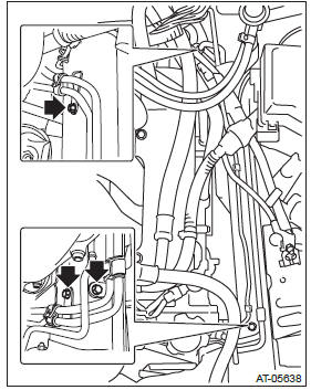
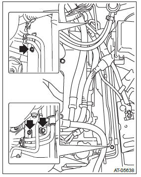
6) Disconnect the ATF radiator inlet and outlet hoses from the radiator.
NOTE:
- Do not use a screwdriver or other pointed tools.
- If it is hard to remove the ATF radiator hose, wrap the hose with cloth to protect it from damage, turn it with pliers, and pull it straight out by hand.
7) Disconnect the ATF AT inlet and outlet hoses from the ATF cooler pipe.
NOTE:
- Do not use a screwdriver or other pointed tools.
- If it is hard to remove the ATF AT hose, wrap the hose with cloth to protect it from damage, turn it with pliers, and pull it straight out by hand.
8) Remove the oil charge pipe. <Ref. to 5AT-62, REMOVAL, Oil Charge Pipe.>
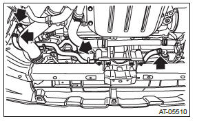
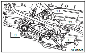
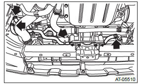
9) Remove the ATF cooler inlet pipe and outlet pipe from the transmission.
NOTE: When disconnecting the ATF cooler outlet pipe, be careful not to lose the ball and spring used together with the retaining screw.
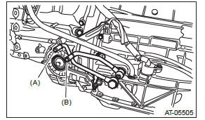
- ATF cooler outlet pipe
- ATF cooler inlet pipe
10) Lower the vehicle.
11) Remove the ATF cooler pipe assembly mounting bolt.
12) Remove the engine coolant reservoir tank.
<Ref. to CO(H6DO)-25, REMOVAL, Reservoir Tank.>
13) Detach the A/C pipe from clip.
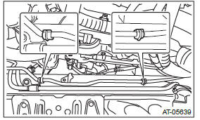
14) Remove the ATF cooler pipe from frame.
CAUTION: Be careful not to bend A/C pipe.
B: INSTALLATION
1) Install the ATF cooler pipe to frame.
CAUTION: Be careful not to bend the A/C pipe, when installing the ATF cooler pipe.
Tightening torque: 7.5 N*m (0.8 kgf-m, 5.5 ft-lb)
2) Install the A/C pipe to clip.
3) Install the engine coolant reservoir tank. <Ref. to CO(H6DO)-25, INSTALLATION, Reservoir Tank.>
4) Lift up the vehicle.
5) Install the ATF cooler inlet and outlet pipes with new gaskets.
NOTE: Use a new bolt for the converter case joint.
Tightening torque:
T1: 38 N*m (3.9 kgf-m, 28.0 ft-lb)
T2: 40 N*m (4.1 kgf-m, 29.5 ft-lb)
T3: 45 N*m (4.6 kgf-m, 33.2 ft-lb)
6) Install the oil charge pipe. <Ref. to 5AT-62, INSTALLATION, Oil Charge Pipe.>
7) Connect the ATF AT inlet and outlet hoses to the ATF cooler pipe on the transmission side.
NOTE:
- Use a new ATF AT hose.
- Install so that the ATF AT hose is not folded over, excessively bent or twisted.
- Insert the ATF AT hose into the specified position.
8) Connect the ATF radiator inlet and outlet hoses to the ATF cooler pipe on radiator side.
NOTE:
- Use a new ATF radiator hose.
- Install so that the ATF radiator hose is not folded over, excessively bent or twisted.
- Insert the ATF radiator hose into the specified position.
9) Install the front exhaust pipe. <Ref. to EX(H6DO)-6, INSTALLATION, Front Exhaust Pipe.>
10) Install the under cover. <Ref. to EI-35, INSTALLATION, Front Under Cover.>
11) Lower the vehicle.
12) Install the battery.
13) Check the ATF level. <Ref. to 5AT-29, INSPECTION, Automatic Transmission Fluid.>
NOTE: Make sure there are no ATF leaks in joints between the transmission, radiator, ATF cooler pipes, and ATF cooler hoses.
14) Install the collector cover.
C: INSPECTION
Repair or replace each faulty ATF hose, ATF cooler pipes, clamps, and washers found in the inspection below.
1) Check for ATF leaks in joints between the transmission, radiator, ATF cooler pipes, and ATF hoses.
2) Check the clamp for deformation.
3) Lightly bend the ATF hose and check for cracks on the surface or other damages.
4) Pinch the ATF hose with your fingers and check for poor elasticity.
5) Check for peeling, cracks, and deformation at the tip of the ATF hose.
Air Breather Hose
A: REMOVAL
1) Remove the collector cover.
NOTE: Follow the steps below when removing the collector cover.
- Pull up the two points at the rear (A).
- Pull up the two points at the front (B) while moving them forward.
2) Remove the air intake boot. <Ref. to IN(H6DO)- 7, REMOVAL, Air Intake Boot.>
3) Remove the air breather hose.
B: INSTALLATION
1) Install the air breather hose.
2) Install the air intake boot. <Ref. to IN(H6DO)-7, INSTALLATION, Air Intake Boot.>
3) Install the collector cover.
C: INSPECTION
Make sure the air breather hose is not cracked or clogged.
READ NEXT:
 Oil Charge Pipe
A: REMOVAL
1) Disconnect the ground cable from battery.
2) Lift up the vehicle.
3) Remove the under cover. <Ref. to EI-35, REMOVAL,
Front Under Cover.>
4) Remove the front exhaust pipe. <R
Extension Case
A: REMOVAL
1) Remove the transmission assembly. <Ref. to
5AT-37, REMOVAL, Automatic Transmission Assembly.>
2) Disconnect the rear vehicle speed sensor connector.
3) Remove the rear vehicle sp
Rear Drive Shaft, Reduction Driven Gear
A: REMOVAL
1) Remove the transmission assembly from the vehicle.
<Ref. to 5AT-37, REMOVAL, Automatic Transmission Assembly.>
2) Remove the rear vehicle speed sensor, and then remove the exten
SEE MORE:
Adjusting the front seat shoulder belt anchor height
The shoulder belt anchor height should be adjusted to the position best suited
for the driver/front passenger. Always adjust the anchor height so that the shoulder
belt passes over the middle of the shoulder without touching the neck.
To raise:
Slide the anchor up.
To lower:
Push the relea
Where to place a child restraint system
The following descriptions are SUBARU’s recommendations on where to place a child
restraint system in your vehicle.
A: Front passenger’s seat
You should not install a child restraint system (including a booster seat) due
to the hazard to children posed by the passenger’s airbag.
B: Re
