Subaru Outback (BR): Oil Charge Pipe
A: REMOVAL
1) Disconnect the ground cable from battery.
2) Lift up the vehicle.
3) Remove the under cover. <Ref. to EI-35, REMOVAL, Front Under Cover.>
4) Remove the front exhaust pipe. <Ref. to EX(H6DO)-5, REMOVAL, Front Exhaust Pipe.>
5) Disconnect the connector from turbine speed sensor 1.
6) Remove the oil charge pipe, and then remove the O-ring from flange side.
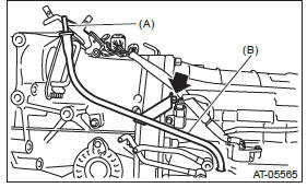
- ATF level gauge (B) Oil charge pipe
B: INSTALLATION
1) Install the oil charge pipe.
NOTE: Use new gaskets and O-rings.
Tightening torque: 38 N*m (3.9 kgf-m, 28.0 ft-lb)
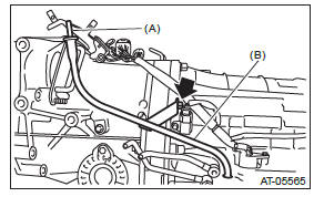
- ATF level gauge
- Oil charge pipe
2) Connect the connector to the turbine speed sensor 1.
3) Install the front exhaust pipe. <Ref. to EX(H6DO)-6, INSTALLATION, Front Exhaust Pipe.>
4) Install the under cover. <Ref. to EI-35, INSTALLATION, Front Under Cover.>
5) Lower the vehicle.
6) Connect the ground cable to battery.
C: INSPECTION
- Make sure the oil charge pipe is not deformed or damaged.
- Check that there are no ATF leaks from the O-ring.
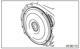
Torque Converter Assembly
A: REMOVAL
1) Remove the transmission assembly from vehicle body. <Ref. to 5AT-37, REMOVAL, Automatic Transmission Assembly.>
2) Pull out the torque converter and oil pump shaft horizontally.
NOTE:
- Be sure not to scratch the inside of bushing in oil pump shaft.
- Be careful that the oil pump shaft may drawn out simultaneously.
3) Remove the oil pump shaft from torque converter as necessary.
B: INSTALLATION
1) When the oil pump shaft is removed, install the shaft to torque converter.
NOTE:
- Use a new circlip.
- Make sure the circlip is firmly inserted.
2) Install the oil pump shaft to torque converter, and then make sure that the clip is secured on groove.
3) Apply ATF to the revolving and sliding surface of the oil pump shaft.
4) Holding the torque converter assembly by hand, lightly rotate it to engage with the oil pump rotor.
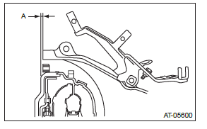
5) Check the protruding dimension of the torque converter assembly.
Dimension A: 8 mm (0.31 in) or less
6) Install the transmission assembly to the vehicle.
<Ref. to 5AT-42, INSTALLATION, Automatic Transmission Assembly.>
C: INSPECTION
Make sure the ring gear and protrusion of torque converter end are not deformed or damaged.
Drive Plate
A: REMOVAL
1) Remove the transmission assembly from the vehicle.
<Ref. to 5AT-37, REMOVAL, Automatic Transmission Assembly.>
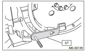
2) Use the ST to lock the crankshaft, and remove the drive plate.
ST 498497100 CRANKSHAFT STOPPER
B: INSTALLATION
1) Temporarily tighten the drive plate.
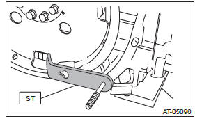
2) Using the ST, lock the crankshaft.
ST 498497100 CRANKSHAFT STOPPER
3) Tighten the drive plate mounting bolt.
NOTE: Tighten the drive plate mounting bolts gradually.
Each bolt should be tightened in a crisscross order.
Tightening torque: 90 N*m (9.2 kgf-m, 66.4 ft-lb)
4) Install the transmission assembly to the vehicle.
<Ref. to 5AT-42, INSTALLATION, Automatic Transmission Assembly.>
READ NEXT:
 Extension Case
A: REMOVAL
1) Remove the transmission assembly. <Ref. to
5AT-37, REMOVAL, Automatic Transmission Assembly.>
2) Disconnect the rear vehicle speed sensor connector.
3) Remove the rear vehicle sp
Rear Drive Shaft, Reduction Driven Gear
A: REMOVAL
1) Remove the transmission assembly from the vehicle.
<Ref. to 5AT-37, REMOVAL, Automatic Transmission Assembly.>
2) Remove the rear vehicle speed sensor, and then remove the exten
Center Differential Carrier
A: REMOVAL
1) Remove the transmission assembly from the vehicle.
<Ref. to 5AT-37, REMOVAL, Automatic
Transmission Assembly.>
2) Remove the rear vehicle speed sensor, and separate
the extension
SEE MORE:
Steps to take if EBD system malfunctions
If a malfunction occurs in the EBD system, the system stops working and the brake
system warning light and ABS warning light illuminate simultaneously.
The EBD system may be malfunctioning if the brake system warning light and ABS
warning light illuminate simultaneously during driving.
Even
3.6 L models
1) Power steering fluid reservoir (page 11-27)
2) Differential gear oil level gauge (page 11-26)
3) Automatic transmission fluid level gauge (page 11-24)
4) Brake fluid reservoir (page 11-28)
5) Fuse box (page 11-46)
6) Battery (page 11-45)
7) Windshield washer tank (page 11-40)
8) Engine o
