Subaru Outback (BR): Center Differential Carrier
A: REMOVAL
1) Remove the transmission assembly from the vehicle.
<Ref. to 5AT-37, REMOVAL, Automatic Transmission Assembly.>
2) Remove the rear vehicle speed sensor, and separate the extension case from transmission case.
<Ref. to 5AT-65, REMOVAL, Extension Case.>
3) Extract the rear drive shaft. <Ref. to 5AT-70, REMOVAL, Rear Drive Shaft.>
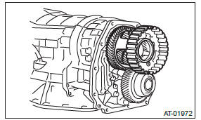
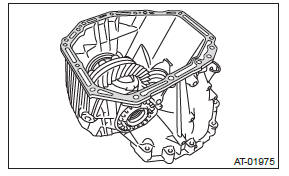
4) Pull out the center differential carrier assembly.
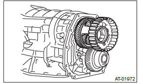
5) Remove the shim from the transmission case.
B: INSTALLATION
1) Install the center differential assembly with the shim(s).
NOTE: Press-fit it to the bottom of bearing shoulder completely.
2) Insert the rear drive shaft. <Ref. to 5AT-70, INSTALLATION, Rear Drive Shaft.>
3) Join the transmission case and the extension case, and then install the rear vehicle speed sensor.
<Ref. to 5AT-65, INSTALLATION, Extension Case.>
4) Install the transmission assembly to the vehicle.
<Ref. to 5AT-42, INSTALLATION, Automatic Transmission Assembly.>
C: DISASSEMBLY
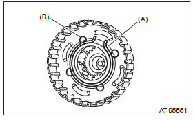
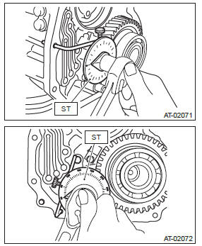
1) Remove the seal ring.
- Seal ring
2) Remove the ball bearing using the ST and the press.
ST 498077600 REMOVER
3) Remove the snap ring, and pull out the pinion shaft from center differential assembly.
- Snap ring
- Pinion shaft
4) Remove the pinion gear and washers from center differential assembly.
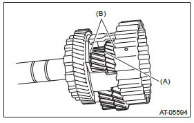
- Pinion gear
- Washer
5) Pull out the intermediate shaft and thrust bearing.
D: ASSEMBLY
1) Install the thrust bearing onto intermediate shaft.
2) Insert the intermediate shaft into the center differential assembly.
3) Install the pinion gears and washers.
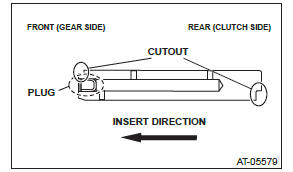
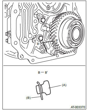
4) Insert the pinion shaft into the center differential assembly.
NOTE:
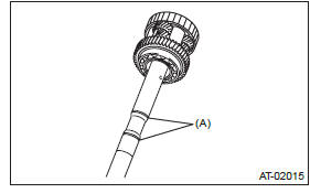
- Insert the pinion shaft with the side with the plug side facing the front side (gear side).
- After inserting the pinion shaft, adjust its position so that the cutout portion on the front side is on the inner side.
5) Install the snap ring.
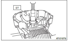
6) Using a press, press-fit the ball bearing into the center differential assembly.
NOTE: Use a new ball bearing.
ST 498077000 REMOVER
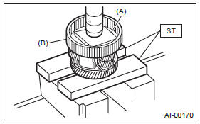
- Plate
- Center differential carrier
7) Apply vaseline onto the seal ring outer surface and shaft grooves.
8) Install a new seal ring.
E: INSPECTION
- Check each parts for holes, damages or other foreign matters.
- Inspect the extension end play, and adjust it to within the standard value. <Ref. to 5AT-67, ADJUSTMENT, Transfer Clutch.>
Parking Pawl
A: REMOVAL
1) Remove the transmission assembly from vehicle body. <Ref. to 5AT-37, REMOVAL, Automatic Transmission Assembly.>
2) Remove the extension case. <Ref. to 5AT-65, REMOVAL, Extension Case.>
3) Remove the center differential carrier. <Ref. to 5AT-74, REMOVAL, Center Differential Carrier.>
4) Remove the front vehicle speed sensor. <Ref. to 5AT-51, REMOVAL, Front Vehicle Speed Sensor.>
5) Remove the parking support actuator.
6) Remove the parking pawl, parking pawl shaft and return spring.
B: INSTALLATION
1) Set the transmission to the N range.
2) Install the parking pawl, parking pawl shaft and return spring.
3) Install the parking support actuator.
Tightening torque: 10 N*m (1.0 kgf-m, 7.4 ft-lb)
4) Using the ST, tighten the bolts which tightened in step 3) with specified angle.
NOTE: Do not use extension as much as possible.
Tightening angle: 17º+-2º
ST 18854AA000 ANGLE GAUGE
5) Make sure that the return spring is sticking out of the parking pole hole.
- Parking pawl
- Return spring
6) Install the front vehicle speed sensor. <Ref. to 5AT-51, INSTALLATION, Front Vehicle Speed Sensor.>
7) Install the center differential carrier. <Ref. to 5AT-74, INSTALLATION, Center Differential Carrier.>
8) Install the extension case. <Ref. to 5AT-65, INSTALLATION, Extension Case.>
9) Install the transmission assembly to the vehicle.
<Ref. to 5AT-42, INSTALLATION, Automatic Transmission Assembly.>
C: INSPECTION
Make sure that the tab of parking pawl on reduction driven gear is not worn or otherwise damaged.
Converter Case
A: REMOVAL
1) Remove the transmission assembly from the vehicle.
<Ref. to 5AT-37, REMOVAL, Automatic Transmission Assembly.>
2) Remove the torque converter assembly. <Ref. to 5AT-63, REMOVAL, Torque Converter Assembly.>
3) Remove the transmission harness connector from stay.
4) Remove the turbine speed sensor 1. <Ref. to 5AT-54, REMOVAL, Turbine Speed Sensor 1.>
5) Remove the air breather hose. <Ref. to 5AT-61, REMOVAL, Air Breather Hose.>
6) Remove the transmission hanger COMPL.
7) Remove the ATF cooler inlet pipe and outlet pipe. <Ref. to 5AT-58, REMOVAL, ATF Cooler Pipe and Hose.>
8) Remove the converter case attachment bolts.
9) Lay along the transmission body, and then remove the oil pan.
10) Remove the three converter case mounting bolts (TORX).
ST 18676AA020 TORX WRENCH
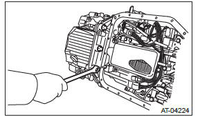
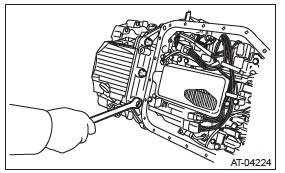
11) Separate the converter case by lightly tapping with plastic hammer.
12) Remove the front differential assembly. <Ref. to 5AT-89, REMOVAL, Front Differential Assembly.>
13) Remove the oil seal from converter case.
B: INSTALLATION
1) Check the appearance of each component and clean them.
2) Press-fit the oil seal to the converter case using ST.
NOTE: Use a new oil seal.
ST 499587100 OIL SEAL INSTALLER
3) Install the front differential assembly and left and right side retainers to the case. <Ref. to 5AT-89, INSTALLATION, Front Differential Assembly.>
4) Remove the oil pump cover from the AT main case, and then adjust and check the backlash and tooth contact of the front differential. <Ref. to 5AT- 80, REMOVAL, Oil Pump Cover.> <Ref. to 5AT-92, ADJUSTMENT, Front Differential Assembly.>
<Ref. to 5AT-86, ADJUSTMENT, Drive Pinion Shaft Assembly.>
5) Apply proper amount of liquid gasket to the entire matching surface of converter case.
Liquid gasket: THREE BOND 1215 (Part No. 004403007) or equivalent
6) Install the converter case assembly without damaging bushing and oil seal.
NOTE: Use a new bolt for the oil charge pipe and ATF cooler pipe portions
Tightening torque:
Oil charge pipe and ATF cooler pipe portions
38 N*m (3.9 kgf-m, 28.0 ft-lb)
Other than above
41 N*m (4.2 kgf-m, 30.2 ft-lb)
7) Install the three converter case mounting bolts (TORX).
Tightening torque: 41 N*m (4.2 kgf-m, 30.2 ft-lb)
ST 18676AA020 TORX WRENCH
8) Apply proper amount of liquid gasket to the entire oil pan mating surface, and then install it.
Liquid gasket: THREE BOND 1217B (Part No. K0877YA020) or equivalent
Tightening torque: 5 N*m (0.5 kgf-m, 3.7 ft-lb)
9) Install the turbine speed sensor 1. <Ref. to 5AT- 54, INSTALLATION, Turbine Speed Sensor 1.>
10) Install the ATF cooler pipe. <Ref. to 5AT-59, INSTALLATION, ATF Cooler Pipe and Hose.>
11) Install the transmission hanger COMPL.
Tightening torque: 41 N*m (4.2 kgf-m, 30.2 ft-lb)
12) Install the transmission harness connector to the stay.
13) Install the air breather hose. <Ref. to 5AT-61, INSTALLATION, Air Breather Hose.>
14) Install the torque converter assembly. <Ref. to 5AT-63, INSTALLATION, Torque Converter Assembly.>
15) Install the transmission assembly to the vehicle.
<Ref. to 5AT-42, INSTALLATION, Automatic Transmission Assembly.>
C: INSPECTION
Measure the backlash, and then adjust it to be within specification. <Ref. to 5AT-86, ADJUSTMENT, Drive Pinion Shaft Assembly.>
READ NEXT:
 Oil Pump Cover removal
A: REMOVAL
1) Remove the transmission assembly from the vehicle.
<Ref. to 5AT-37, REMOVAL, Automatic Transmission Assembly.>
2) Pull out the torque converter assembly. <Ref. to 5AT-63, REM
Drive Pinion Shaft Assembly in Automatic Transmission
A: REMOVAL
1) Remove the transmission assembly from the vehicle.
<Ref. to 5AT-37, REMOVAL, Automatic Transmission Assembly.>
2) Pull out the torque converter assembly. <Ref. to 5AT-63, REM
AT Main Case
A: REMOVAL
1) Remove the transmission assembly from the vehicle.
<Ref. to 5AT-37, REMOVAL, Automatic
Transmission Assembly.>
2) Pull out the torque converter assembly. <Ref. to
5AT-63, REMO
SEE MORE:
Front Grille
A: REMOVAL
1) Remove the front bumper face assembly.
Remove the clips, turn over the front mud guard, and disconnect the fog
light connector. (Model with
fog light)
Remove the clips at the upper side of the bumper.
Remove the clips from the fender.
Remove the clips at the lower side of bu
Front Arm
A: REMOVAL
1) Lift up the vehicle, and then remove the front wheels.
2) Remove the front arm.
Remove the nut and disconnect the front stabilizer link.
Remove the bolt, and then remove the ball joint for the front arm.
Remove the bolts, then remove the front arm.
B: INSTALLATION
1) Before i
