Subaru Outback (BR): HVAC System Control Panel
A: REMOVAL
1. AUTO A/C MODEL
1) Disconnect the ground cable from battery.
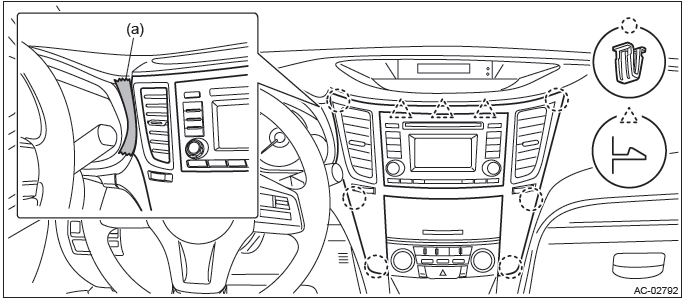
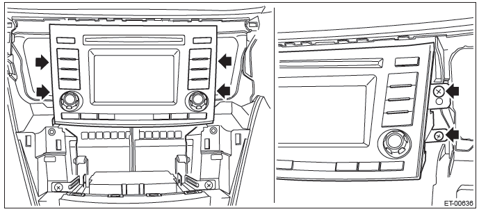
2) Remove the center panel assembly.
CAUTION: Do not put your finger on the fin of the air vent grille. Doing so may damage the fin.
- Attach the protective tape (a) to the meter visor.
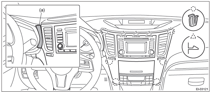
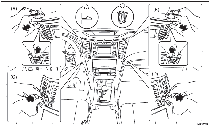
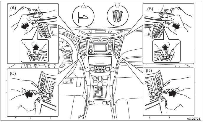
- Insert a finger into the air vent grille and release the left and right clips at the top of the center panel.
(A), (B)
- Insert a finger into the air vent grille and release the left and right clips at the center of the center panel.
(C), (D)
- Release the clips at the bottom of the center panel and remove the center panel assembly.
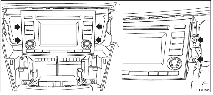
3) Remove the audio assembly.
- Remove the left and right screws, and partially pull the audio out from center console.
- Disconnect the connectors, and remove the audio assembly.
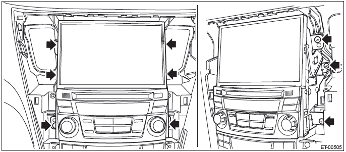
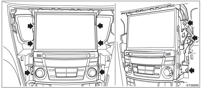
4) Remove the navigation assembly. (model with navigation)
- Remove the left and right screws.
- Disconnect the connectors, and remove the navigation assembly.
5) Remove the control panel.
- Remove the screws and release the clip.
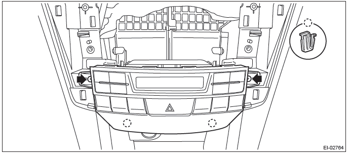
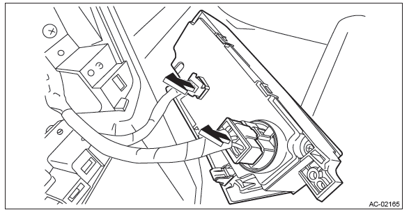
- Pull forward the control module and disconnect the connector.
2. MANUAL A/C MODEL
1) Disconnect the ground cable from battery.
2) Remove the center panel assembly.
CAUTION: Do not put your finger on the fin of the air vent grille. Doing so may damage the fin.
- Attach the protective tape (a) to the meter visor.
- Insert a finger into the air vent grille and release the left and right clips at the top of the center panel.
(A), (B)
- Insert a finger into the air vent grille and release the left and right clips at the center of the center panel.
(C), (D)
- Release the clips at the bottom of the center panel and remove the center panel assembly.
3) Remove the audio assembly.
- Remove the left and right screws, and partially pull the audio out from center console.
- Disconnect the connectors, and remove the audio assembly.
4) Remove the navigation assembly. (model with navigation)
- Remove the left and right screws.
- Disconnect the connectors, and remove the navigation assembly.
5) Remove the control panel.
- Remove the screws and release the clip.
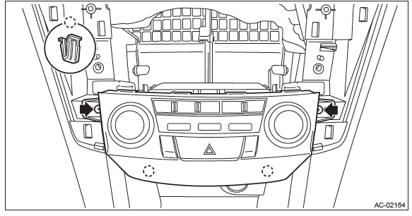
- Pull the control panel and disconnect the connector.
B: INSTALLATION
Install each part in the reverse order of removal.
C: INSPECTION
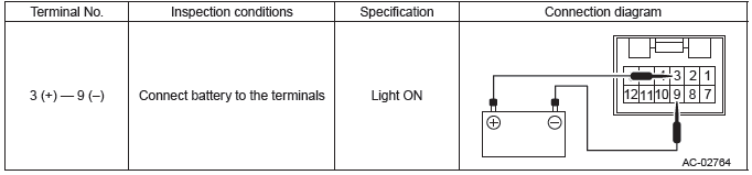
1. CHECK ILLUMINATION
1) Check the illumination operation when battery voltage is applied between the terminals of control panel.
- Auto A/C model
- Manual A/C model
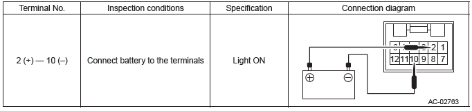
2) If the illumination does not operate normally, replace the control panel.
2. BLOWER SWITCH (MANUAL A/C MODEL)
Preparation tool: Circuit tester
1) Check the resistance between terminals of the control panel.
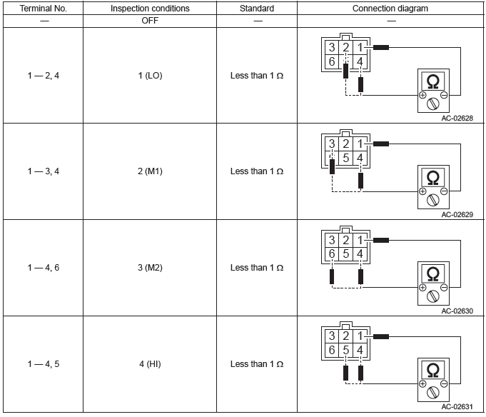
2) Replace the control panel if the inspection result is not within the standard value.
Control Unit
A: REMOVAL
1) Disconnect the ground cable from battery.
2) Remove the glove box. <Ref. to EI-66, REMOVAL, Glove Box.>
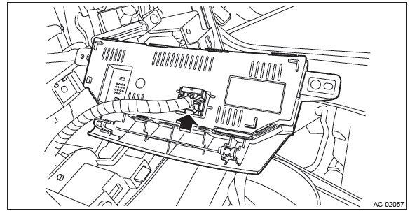
3) Remove the control module.
- Release the lock and remove the relay bracket.
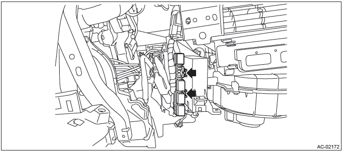
- Disconnect the connector.
- Remove the screws, and remove the control module.
B: INSTALLATION
Install each part in the reverse order of removal.
Compressor
A: REMOVAL
1) Perform compressor oil return operation. <Ref. to AC-31, PROCEDURE, Compressor Oil.>
2) Turn the A/C switch to OFF and stop the engine.
3) Using the refrigerant recovery system, discharge refrigerant. <Ref. to AC-24, PROCEDURE, Refrigerant Recovery Procedure.>
4) Disconnect the ground cable from battery.
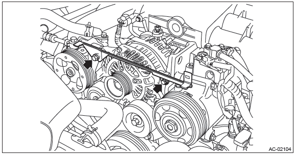
5) Remove the V-belts.
- H4 non-turbo model: <Ref. to ME(H4SO)-43, REMOVAL, V-belt.>
- H4 turbo model: <Ref. to ME(H4DOTC)-42, REMOVAL, V-belt.>
- H6 model: <Ref. to ME(H6DO)-51, REMOVAL, V-belt.>
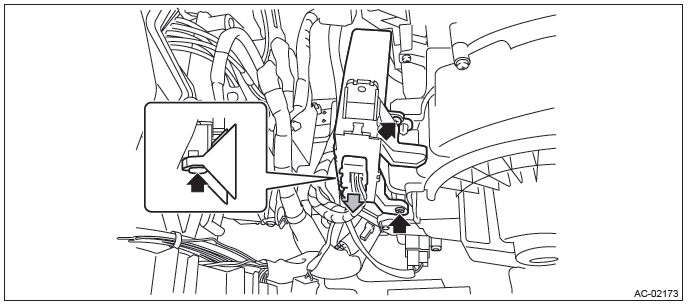
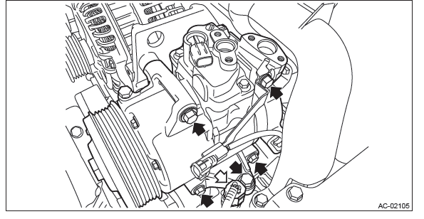
6) Move the alternator harness to the right.
- Remove the nuts and connector.
- Release the lock and move the alternator harness to the right.
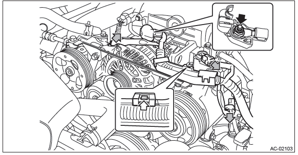
7) Remove the bolts and then remove the collector cover bracket.
8) Remove the bolt and remove the low-pressure hose and high-pressure hose.
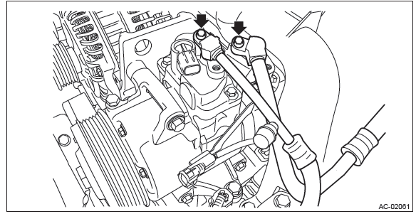
9) Remove the compressor.
- Disconnect the water temperature sensor connector.
- Remove the bolts and remove the compressor.
NOTE:
- Since the compressor cannot be removed by itself, remove it with the loosened bolts inserted in the bracket.
- Be careful not to damage the pulley and sensor.
B: INSTALLATION
CAUTION:
- Replace the O-rings on low/high pressure hoses with new parts, and apply compressor oil.
- If the compressor is replaced, adjust the amount of the compressor oil. <Ref. to AC-31, PROCEDURE, Compressor Oil.>
- After installing the compressor, do not start the engine until the A/C system is charged with refrigerant.
- If the engine is started with no refrigerant charge, replace the compressor.
1) Install each part in the reverse order of removal.
2) Charge refrigerant. <Ref. to AC-25, PROCEDURE, Refrigerant Charging Procedure.>
3) After installing the compressor, perform a break-in operation according to the following steps.
NOTE: Do not increase the engine speed to and above 4,000 rpm unless the break-in operation finishes.
- Check that all connectors are locked securely.
- Reset the control module. (Disconnect and then connect the connector)
- Attach a delivery (test) mode fuse to the main fuse box.
- Set the airflow adjustment dial to MAX (4th position). (manual A/C model)
- Connect the Subaru Select Monitor, select {Variable compressor break-in drive} mode and display the current data {Variable compressor break-in drive finish status} by following the procedure.
- Start and idle the engine at or below 1,800 rpm. (The compressor operation is automatically changed to the break-in operation mode.)
- When {Variable compressor break-in drive finish status} changes from "incomplete" to "Finished", stop the engine.
CAUTION: If the engine may have been started with no refrigerant charge, check for any diagnosis code (DTC) using Subaru Select Monitor. If the code B1644 (Refrigerant not sealed drive error) is output, replace the compressor.
(8) Remove the delivery (test) mode fuse from the main fuse box.
(9) The break-in operation finishes.
Tightening torque:
Air conditioning unit: <Ref. to AC-10, AIR CONDITIONING UNIT, COMPONENT, General Description.>
Compressor: <Ref. to AC-11, COMPRESSOR, COMPONENT, General Description.>
Condenser
A: REMOVAL
1) Using the refrigerant recovery system, drain the refrigerant. <Ref. to AC-24, PROCEDURE, Refrigerant Recovery Procedure.>
2) Remove the clips and remove the air intake duct.
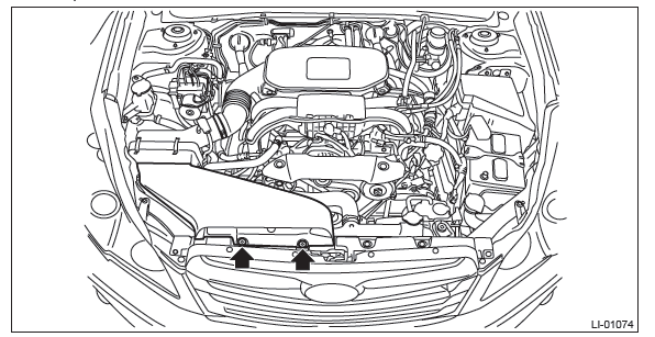
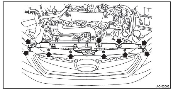
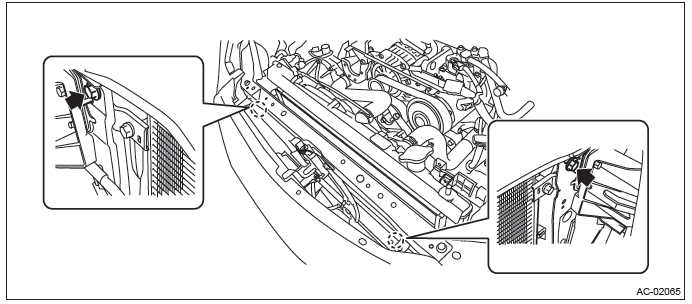
3) Remove the clips and remove the grille bracket.
NOTE: To prevent damage to the grille bracket, make sure to remove all clips.
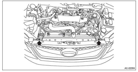
4) Remove the bolts and disconnect the high pressure hose and A/C pipe from the condenser.

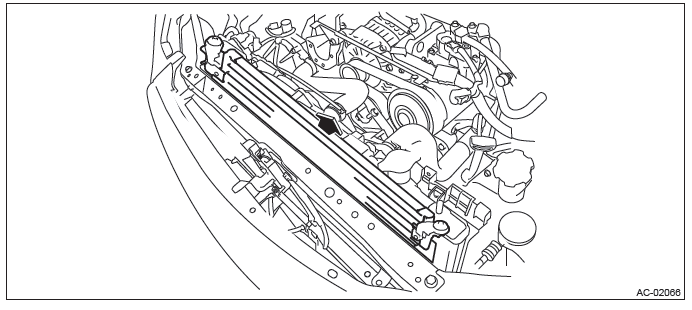
5) Remove the bolts and remove the radiator upper bracket.
6) Remove the condenser.
- Remove the bolt.
- By lifting the condenser, pull it out through the space between the radiator and the radiator panel.
CAUTION: Be careful not to damage the condenser fins. If a damaged fin is found, repair it using a thin screwdriver.
B: INSTALLATION
CAUTION:
- Do not start the engine before charging refrigerant.
- If the engine is started with no refrigerant charge, replace the compressor.
- If the condenser has been replaced, add an appropriate amount of compressor oil to the compressor.
<Ref. to AC-31, REPLACEMENT, Compressor Oil.>
- Replace the O-rings with new parts, and then apply compressor oil.
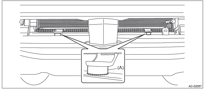
- Confirm that lower guide (A) of condenser fits into holes on radiator panel.
1) Install each part in the reverse order of removal.
2) Charge refrigerant. <Ref. to AC-25, PROCEDURE, Refrigerant Charging Procedure.>
Tightening torque:
Air conditioning unit: <Ref. to AC-10, AIR CONDITIONING UNIT, COMPONENT, General Description.>
Radiator bracket: <Ref. to CO(H4DOTC)-4, RADIATOR AND RADIATOR FAN, COMPONENT, General Description.>
C: INSPECTION
1) Check to see that the condenser fins are not clogged with debris or insects. Blow with compressed air or flush fins with water as needed.
2) If any oil leak is found from the condenser, replace the condenser.
READ NEXT:
 Heater and Cooling Unit
A: REMOVAL
1) Disconnect the ground cable from battery.
2) Using the refrigerant recovery system, discharge refrigerant. <Ref. to AC-24,
PROCEDURE, Refrigerant
Recovery Procedure.>
3) Drain t
Evaporator
A: REMOVAL
1) Disconnect the ground cable from battery.
2) Using the refrigerant recovery system, discharge refrigerant. <Ref. to AC-24,
PROCEDURE, Refrigerant
Recovery Procedure.>
3) Drain t
Expansion Valve
A: REMOVAL
1) Disconnect the ground cable from battery.
2) Using the refrigerant recovery system, discharge refrigerant. <Ref. to AC-24,
PROCEDURE, Refrigerant
Recovery Procedure.>
3) Remove
SEE MORE:
Side Airbag Module
A: REMOVAL
CAUTION:
Refer to "CAUTION" of "General Description" before handling the airbag module.
<Ref. to AB-9,
CAUTION, General Description.>
NOTE:
Remove the passenger's side by referring to driver's side.
1) Remove the headrest.
NOTE:
For models with headrest monitor, remove the headrest
Photosensors
The mirror has a photosensor attached on both the front and back sides. During
nighttime driving, these sensors detect distracting glare from vehicle headlights
behind you and automatically dim the mirror to eliminate glare and preserve your
vision. For this reason, use care not to cover the
