Subaru Outback (BR): General Description of Clutch System
Subaru Outback (BR) 2010-2015 Service Manual / Transmission / Clutch System / General Description of Clutch System
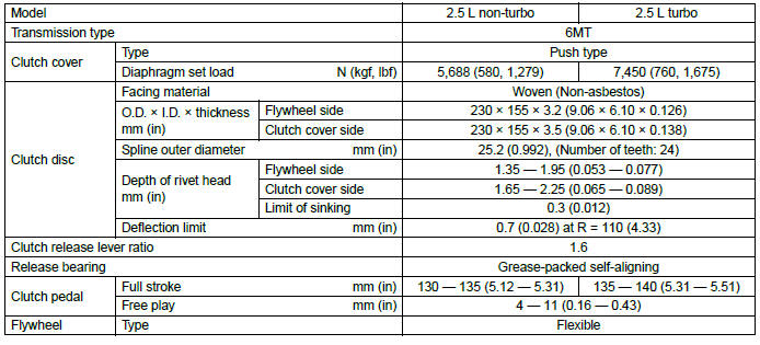
A: SPECIFICATION
B: COMPONENT
1. CLUTCH ASSEMBLY
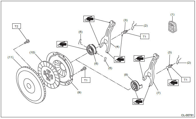
- Dust cover
- Lever spring
- Pivot
- Release lever (non-turbo model)
- Clip (non-turbo model)
- Release bearing (non-turbo model)
- Release lever (turbo model)
- Release bearing (turbo model)
- Clutch cover
- Clutch disc
- Flexible flywheel
Tightening torque: N*m (kgf-m, ft-lb)
T1: 16 (1.6, 11.8)
T2: 75 (7.6, 55.3)
2. CLUTCH PIPE AND HOSE
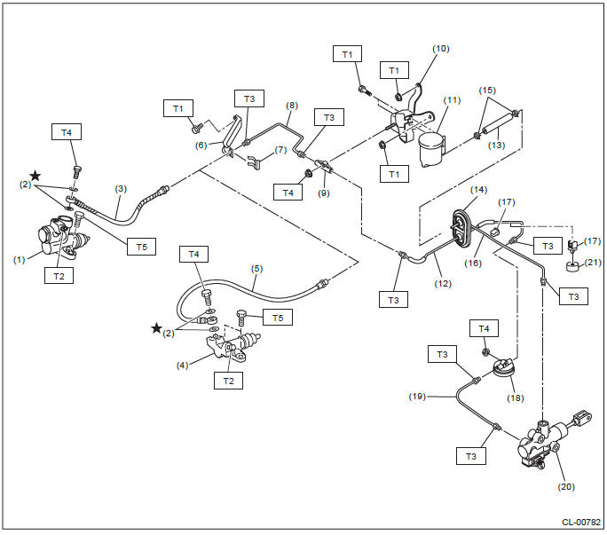
- Operating cylinder (turbo model)
- Washer
- Clutch hose (turbo model)
- Operating cylinder (non-turbo model)
- Clutch hose (non-turbo model)
- Clutch hose bracket
- Clamp
- Clutch pipe
- Connector
- Reservoir tank bracket
- Reservoir tank
- Clutch pipe
- Reservoir tank hose
- Clutch pipe grommet
- Clamp
- Clutch pipe
- Clamp
- Clutch damper
- Clutch pipe
- Master cylinder ASSY
- Mass damper
Tightening torque: N*m (kgf-m, ft-lb)
T1: 7.5 (0.8, 5.5)
T2: 7.8 (0.8, 5.8)
T3: 15 (1.5, 11.1)
T4: 18 (1.8, 13.3)
T5: 37 (3.8, 27.3)
3. MASTER CYLINDER
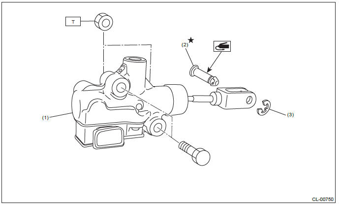
- Master cylinder ASSY
- Clevis pin
- Clip
Tightening torque: N*m (kgf-m, ft-lb)
T: 18 (1.8, 13.3)
4. OPERATING CYLINDER
- Non-turbo model
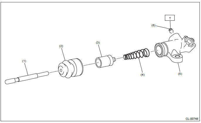
- Push rod
- Boot
- Piston
- Piston spring
- Operating cylinder
- Breather screw
Tightening torque: N*m (kgf-m, ft-lb)
T: 7.8 (0.8, 5.8)
- Turbo model
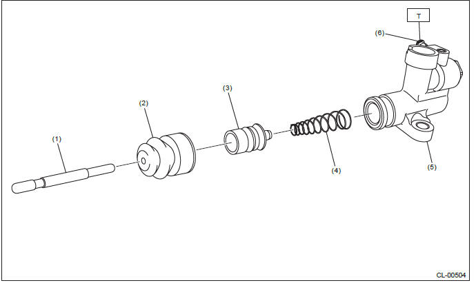
- Push rod
- Boot
- Piston
- Piston spring
- Operating cylinder
- Breather screw
Tightening torque: N*m (kgf-m, ft-lb)
T: 7.8 (0.8, 5.8)
5. CLUTCH PEDAL ASSEMBLY
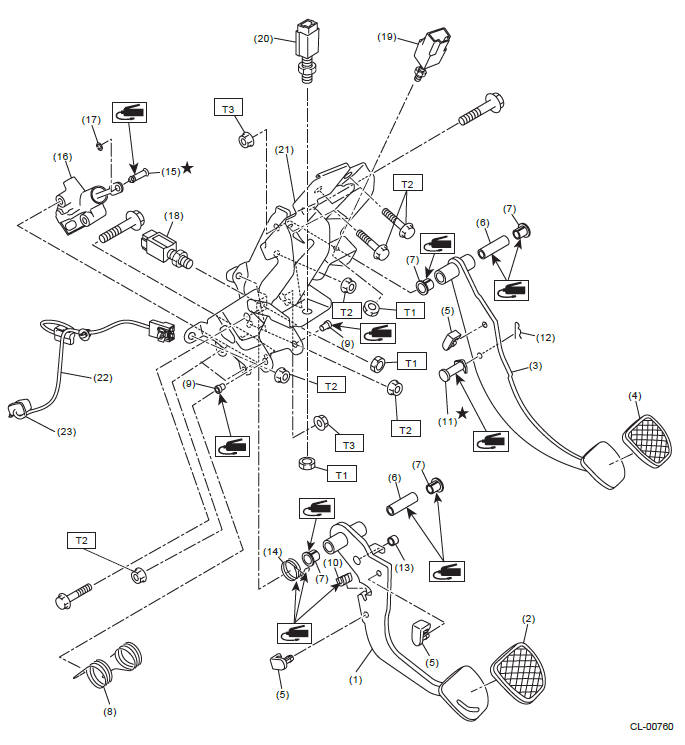
- Clutch pedal
- Clutch pedal pad
- Brake pedal
- Brake pedal pad
- Stopper
- Spacer
- Bushing
- Torsion spring
- Assist bushing
- Torsion spring bushing
- Clevis pin
- Snap pin
- Bushing A
- Assist spring (turbo model)
- Clevis pin
- Master cylinder ASSY
- Clip
- Clutch start switch
- Stop & brake switch
- Clutch switch
- Pedal bracket
- Sensor harness
- Band
Tightening torque: N*m (kgf-m, ft-lb)
T1: 8 (0.8, 5.9)
T2: 18 (1.8, 13.3)
T3: 30 (3.1, 22.1)
C: CAUTION
- Wear appropriate work clothing, including a cap, protective goggles and protective shoes when performing any work.
- Remove contamination including dirt and corrosion before removal, installation or disassembly.
- Keep the disassembled parts in order and protect them from dust and dirt.
- Before removal, installation or disassembly, be sure to clarify the failure. Avoid unnecessary removal, installation, disassembly and replacement.
- Vehicle components are extremely hot after driving. Be wary of receiving burns from heated parts.
- Use SUBARU genuine fluid, grease etc. or equivalent. Do not mix fluid, grease, etc. of different grades or manufacturers.
- Be sure to tighten fasteners including bolts and nuts to the specified torque.
- Place shop jacks or rigid racks at the specified points.
- Apply grease onto sliding or revolving surfaces before installation.
- Before installing O-rings or snap rings, apply sufficient amount of fluid to avoid damage and deformation.
- Before securing a part in a vise, place cushioning material such as wood blocks, aluminum plate or cloth between the part and the vise.
- Keep fluids away from the vehicle body. If any fluid contacts the vehicle body, immediately flush the area with water.
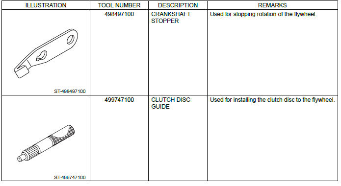
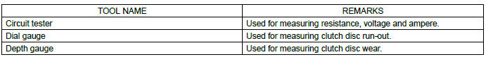
D: PREPARATION TOOL
1. SPECIAL TOOL
2. GENERAL TOOL
READ NEXT:
 Clutch Disc and Cover
A: REMOVAL
1) Remove the transmission assembly from vehicle
body. <Ref. to 6MT-25, REMOVAL, Manual Transmission
Assembly.>
2) Attach the ST to the flywheel.
ST 499747100 CLUTCH DISC GUIDE
C
Flywheel
A: REMOVAL
1) Remove the transmission assembly. <Ref. to
6MT-25, REMOVAL, Manual Transmission Assembly.>
2) Remove the clutch cover and clutch disc. <Ref.
to CL-11, REMOVAL, Clutch Disc and
Operating Cylinder
A: REMOVAL
NOTE:
The illustration below is suitable for every model.
Perform the same procedures for the other models.
1) Remove the collector cover. (turbo model)
2) Remove the air intake boot ass
SEE MORE:
CVTF Cooler Pipe and Hose
A: REMOVAL
CAUTION:
Immediately after the vehicle has been running or after idling for a
long time, the CVTF will be hot.
Be careful not to burn yourself.
If the CVTF is spilt over exhaust pipe, wipe it off with cloth to
avoid emitting smoke or causing a
fire.
When removing the CVTF cooler
To arm the system using power door locking switch
1. Close all windows.
2. Remove the key from the ignition switch.
3. Open the doors and get out of the vehicle.
4. Make sure that the engine hood is locked.
5. Close the doors (and the rear gate (Outback)) but leave only the driver’s door
or the front passenger’s door open.
6. Press the
© 2010-2026 Copyright www.suoutback.com
