Subaru Outback (BR): General Description of Power Assisted System
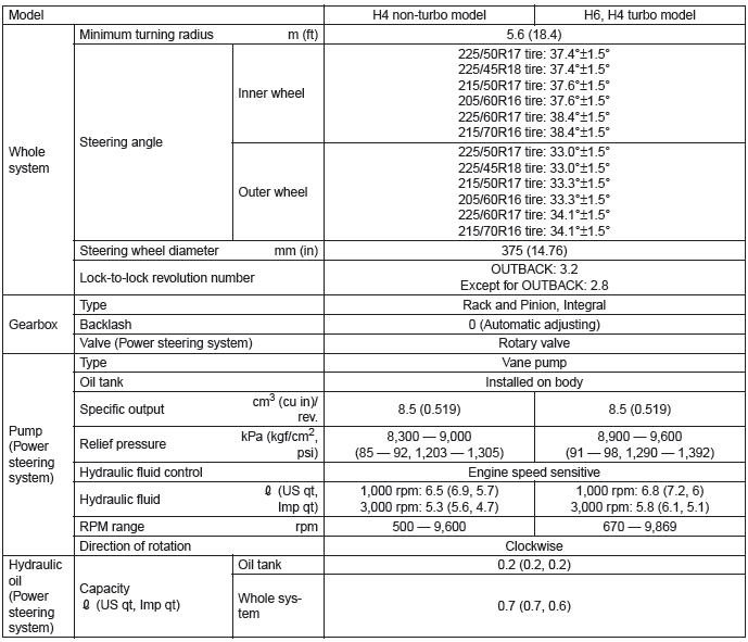
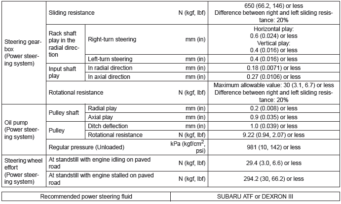
A: SPECIFICATION

B: COMPONENT
1. STEERING WHEEL AND COLUMN
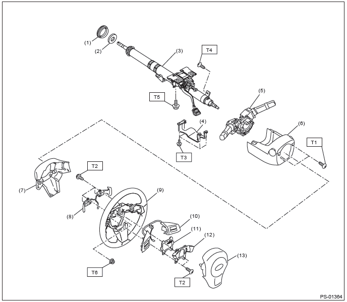
- Bushing
- Insulator (CVT model)
- Steering shaft
- Knee protector
- Steering roll connector
- Column cover
- Steering wheel lower cover
- Paddle shift
- Steering wheel
- Switch
- Protector
- Dynamic damper
- Airbag module
Tightening torque:N*m (kgf-m, ft-lb)
T1: 1.2 (0.12, 0.9)
T2: 1.7 (0.17, 1.3)
T3: 3.4 (0.35, 2.5)
T4: 3.5 (0.36, 2.6)
T5: 20 (2.04, 14.8)
T6: 39 (3.98, 28.8)
2. HOSE AND TANK
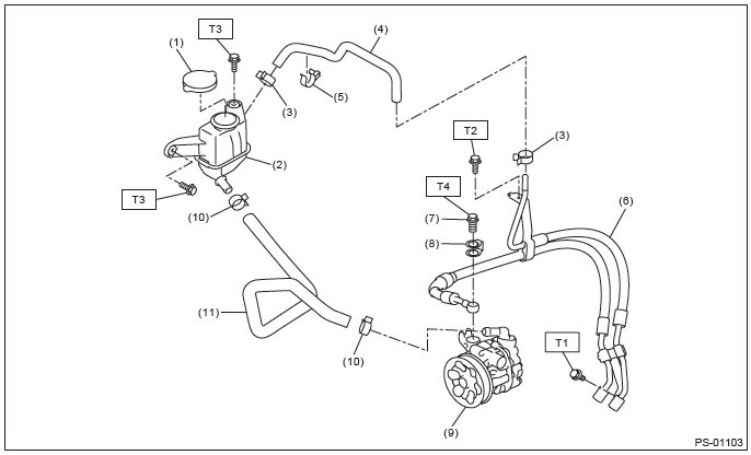
- Cap
- Reservoir tank
- Clip
- Return hose
- Clip
- Hose ASSY
- Eye bolt
- Eye bolt gasket
- Oil pump
- Clip
- Suction hose
Tightening torque:N*m (kgf-m, ft-lb)
T1: 7.5 (0.76, 5.5)
T2: 10 (1.02, 7.4)
T3: 13 (1.33, 9.6)
T4: 40 (4.08, 29.5)
3. STEERING GEARBOX
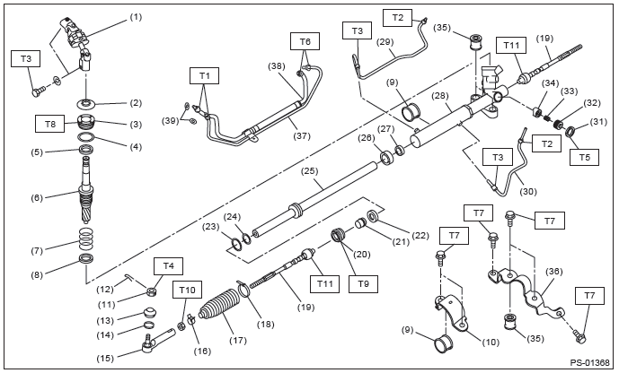
- Universal joint
- Dust cover
- Plug
- O-ring
- Oil seal
- Control valve
- Seal ring
- Oil seal
- Adapter
- Clamp
- Castle nut
- Cotter pin
- Dust seal
- Clip
- Tie-rod end
- Clip
- Boot
- Band
- Tie-rod
- Holder
- Bushing
- Oil seal
- Seal ring
- O-ring
- Rack
- Oil seal
- Back-up ring
- Steering body
- Pipe A
- Pipe B
- Lock nut
- Adjusting screw
- Spring
- Sleeve
- Bushing
- Stiffener
- Feed pipe
- Return pipe
- O-ring
Tightening torque:N*m (kgf-m, ft-lb)
T1: 15 (1.53, 11.1)
T2: 20 (2.04, 14.8)
T3: 24 (2.45, 17.7)
T4: 27 (2.75, 19.9)
T5: 39 (3.98, 28.8)
T6: 45 (4.59, 33.2)
T7: 60 (6.12, 44.3)
T8: 64 (6.53, 47.2)
T9: 75 (7.65, 55.3)
T10: 85 (8.67, 62.7)
T11: 90 (9.18, 66.4)
4. OIL PUMP
- H4 non-turbo model
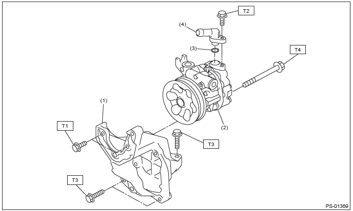
- Bracket
- Oil pump
- O-ring
- Joint
Tightening torque:N*m (kgf-m, ft-lb)
T1: 16 (1.63, 11.8)
T2: 21 (2.14, 15.5)
T3: 22 (2.24, 16.2)
T4: 36 (3.67, 26.6)
- H4 turbo model
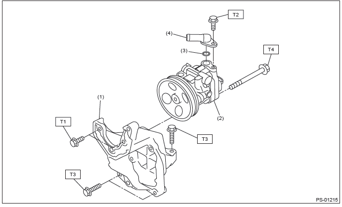
- Bracket
- Oil pump
- O-ring
- Joint
Tightening torque:N*m (kgf-m, ft-lb)
T1: 16 (1.63, 11.8)
T2: 21 (2.14, 15.5)
T3: 22 (2.24, 15.9)
T3: 22 (2.24, 15.9)
- H6 model
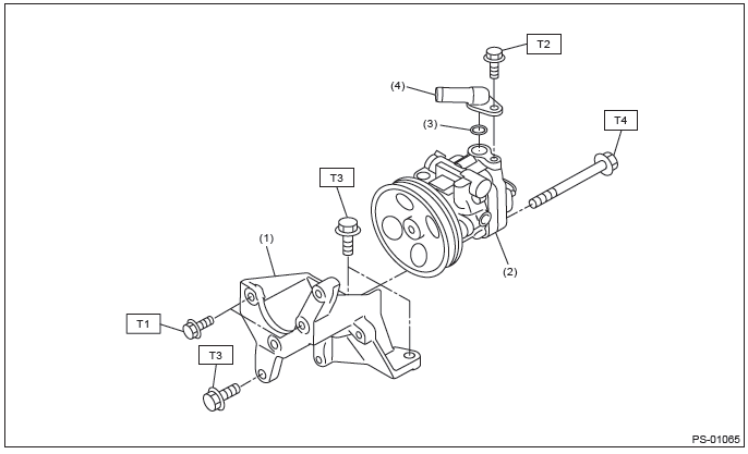
- Bracket
- Oil pump
- O-ring
- Joint
Tightening torque:N*m (kgf-m, ft-lb)
T1: 16 (1.63, 11.8)
T2: 21 (2.14, 15.5)
T3: 33 (3.36, 24.3)
T4: 36 (3.67, 26.6)
C: CAUTION
- Wear appropriate work clothing, including a helmet, protective goggles and protective shoes when performing any work.
- Before removal, installation or disassembly, be sure to clarify the failure. Avoid unnecessary removal, installation, disassembly and replacement.
- Vehicle components are extremely hot after driving. Be wary of receiving burns from heated parts.
- Use grease and oil of Subaru genuine or the equivalent products. Do not mix them of different grades or manufacturers.
- Be sure to tighten fasteners including bolts and nuts to the specified torque.
- Place shop jacks or rigid racks at the specified points.
- Before securing a part on a vise, place cushioning material such as wooden blocks, aluminum plate or cloth between the part and the vise.
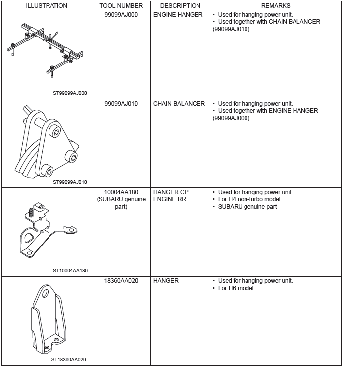
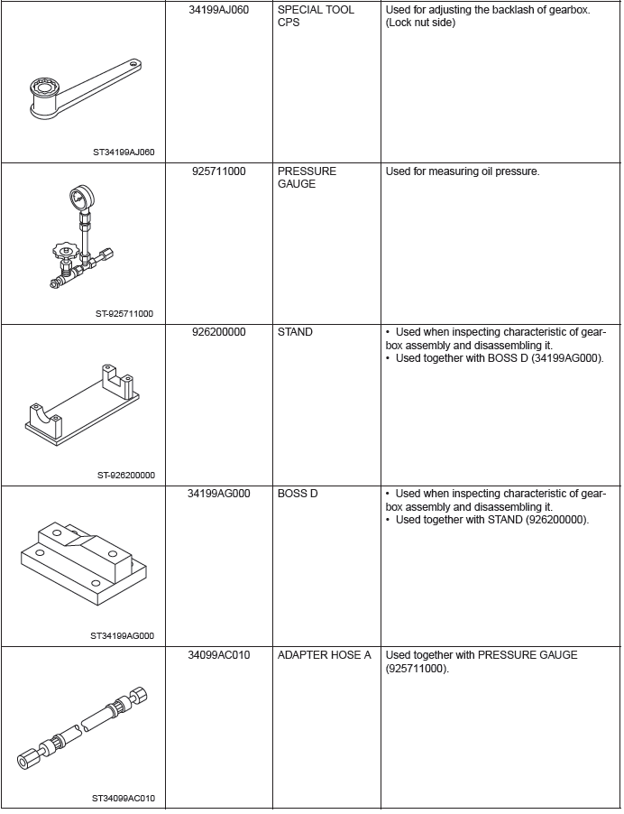
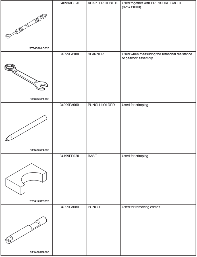
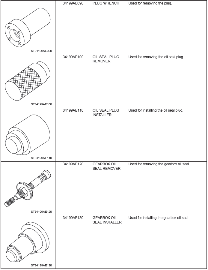
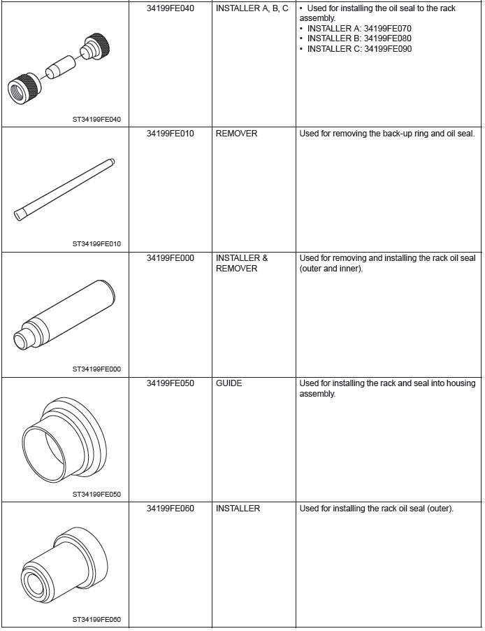
D: PREPARATION TOOL
1. SPECIAL TOOL
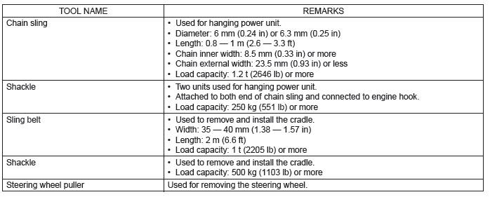
2. GENERAL TOOL
READ NEXT:
 Steering Wheel
A: REMOVAL
1) Disconnect the negative terminal from the battery, and wait for 60 seconds
or more.
2) Set the tire to the straight-ahead position.
3) Remove the driver's airbag module assembly.
Pu
Universal Joint
A: REMOVAL
1) Adjust the tilt position of the steering column to the lowest position and
lock the tilt lever.
2) Prevent the steering wheel from turning using the seat belt.
3) Remove the universal
Steering Column
A: REMOVAL
1) Adjust the tilt position to the lowest position and lock the tilt lever.
2) Remove the driver's airbag module assembly.
Push in the snap pin using a hexagon wrench or equivalent wrapp
SEE MORE:
Wiper Blade
A: REMOVAL
1. FRONT
Remove the blade assembly.
1) Lift up the locking clip (A).
2) Turn the blade assembly in the arrow direction.
3) Press the arm in.
4) Pull out the arm while lifting it, and remove the blade assembly from the
arm.
2. REAR
Turn the blade in the direction of arrow (A) and remo
Towing with all wheels on the ground
WARNING
● Never turn the ignition switch to the “LOCK” position while the vehicle is
being towed because the steering wheel and the direction of the wheels will be locked.
● Remember that the brake booster and power steering do not function when the
engine is not running. Bec
