Subaru Outback (BR): General Description of Heater, Ventilator, A/C
A: SPECIFICATION
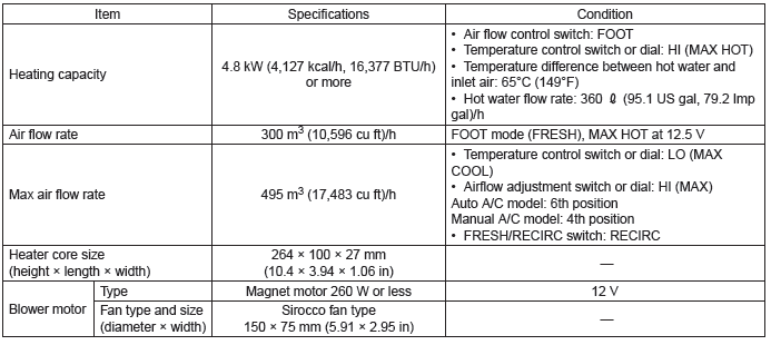
1. HEATER SYSTEM
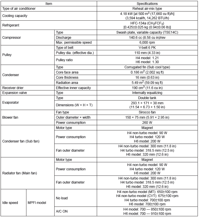
2. A/C SYSTEM
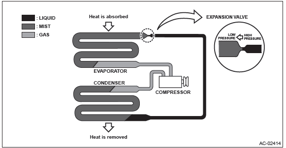
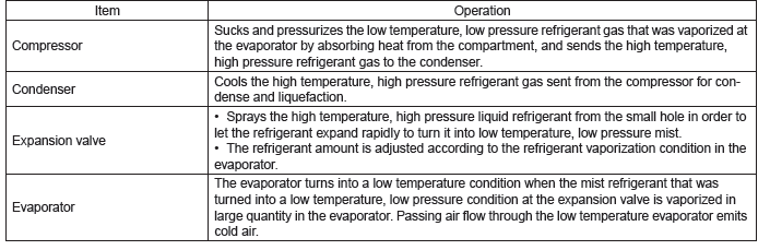
3. BASIC OPERATION
The cooling system cools down the compartment by using the pipes connecting parts and cycling the evaporable liquid (refrigerant) within the sealed system in a repeated process of "vaporization - liquefaction - re-vaporization".
B: LOCATION
1. ELECTRICAL PARTS (ACTUATORS AND SENSORS)
- Engine compartment
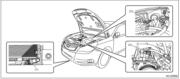
- Ambient sensor
- Pressure sensor
- Flow sensor
- Compartment
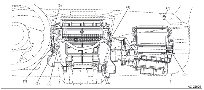
- Air mix door actuator (driver's seat)
- In-vehicle sensor
- Evaporator sensor
- Air mix door actuator (passenger's seat)
- Intake door actuator
- Mode door actuator
- Sunload sensor
C: COMPONENT
1. HEATER COOLING UNIT
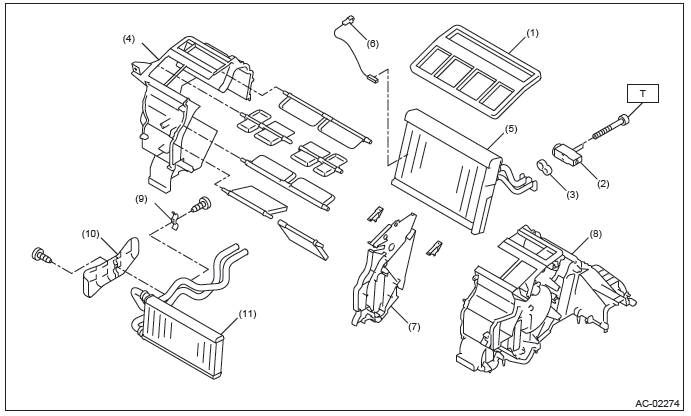
- Lining
- Expansion valve
- Gasket
- Heater case LH
- Evaporator
- Evaporator sensor
- Center plate
- Heater case RH
- Heater pipe clamp
- Heater pipe cover
- Heater core ASSY
Tightening torque: N*m (kgf-m, ft-lb)
T: 3.5 (0.36, 2.6)
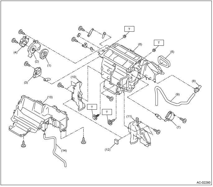
- Mode main lever
- Cover
- Air mix actuator (driver's seat)
- Mode actuator
- Gasket
- Unit ASSY
- Air mix actuator (passenger's seat)
- Aspirator
- Aspirator hose
- Foot duct LH
- Foot duct RH
- Gasket
- Heater case lower
- Drain hose
Tightening torque: N*m (kgf-m, ft-lb)
T: 7.5 (0.76, 5.5)
2. BLOWER MOTOR UNIT
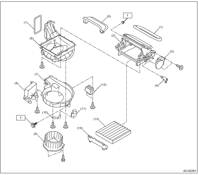
- Gasket
- Air duct cover ASSY
- Intake door actuator
- Intake door link
- FRESH/RECIRC door
- Upper case
- Lower case
- Control module
- Blower motor ASSY
- Relay holder bracket
- Blower motor relay
- Power transistor (auto A/C model) or resistor (manual A/C)
- Filter
- Filter cover
Tightening torque: N*m (kgf-m, ft-lb)
T: 7.5 (0.76, 5.5)
3. CONTROL MODULE
- AUTO A/C MODEL
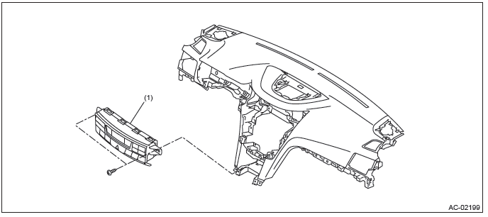
- Control module
- MANUAL A/C MODEL
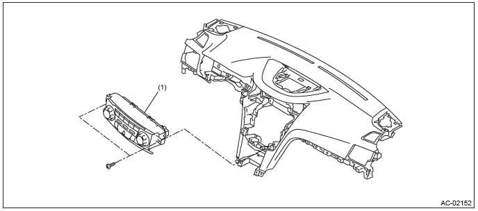
- Control module
4. AIR CONDITIONING UNIT
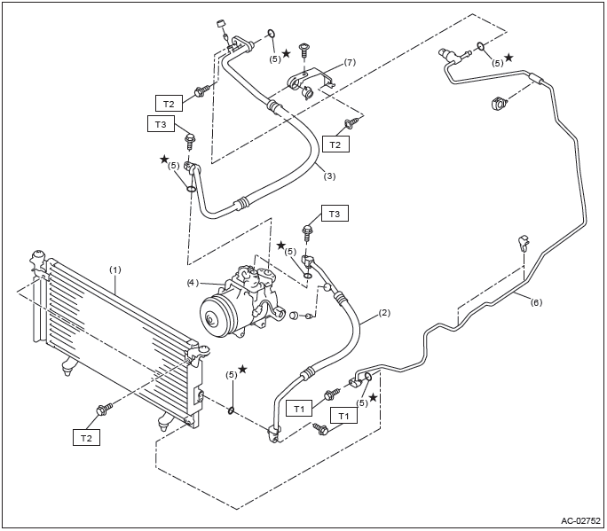
- Condenser
- Hose (high-pressure)
- Hose (low-pressure)
- Compressor
- O-ring
- Pipe
- Bracket
Tightening torque: N*m (kgf-m, ft-lb)
T1: 5 (0.51, 3.7)
T2: 7.5 (0.76, 5.5)
T3: 10 (1.02, 7.4)
5. COMPRESSOR
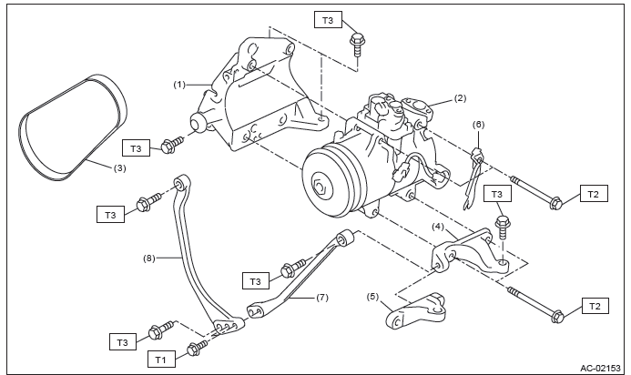
- A/C compressor stay
- Compressor
- V-belt (6 PK)
- Compressor bracket (H4 model)
- Compressor bracket (H6 model)
- Connector bracket
- Stopper rod LH (H4 model)
- Stopper rod RH (H4 model)
Tightening torque: N*m (kgf-m, ft-lb)
T1: 22 (2.24, 16.2)
T2: 26.5 (2.70, 19.5)
T3: 36 (3.67, 26.6)
6. HEATER DUCT
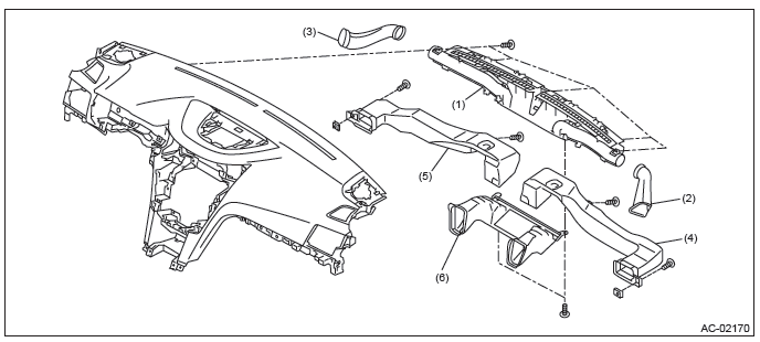
- Defroster nozzle ASSY
- Side defroster duct RH
- Side defroster duct LH
- Side vent duct RH
- Side vent duct LH
- Front vent duct
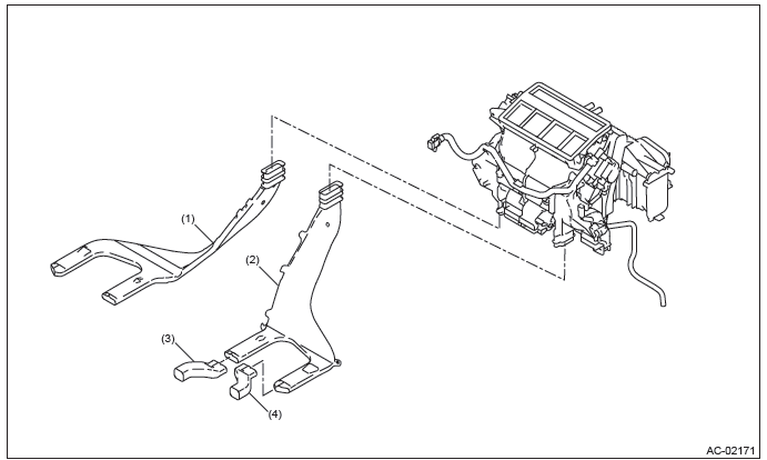
- Rear heater duct LH
- Rear heater duct RH
- Extension duct LH
- Extension duct RH
D: CAUTION
- Before disassembling or reassembling parts, always disconnect the battery ground cable from battery.
When replacing the radio, control module, and other parts provided with memory functions, record the memory contents before disconnecting the battery ground cable. Otherwise, the memory is cleared.
- Reassemble the parts in the reverse order of disassembly procedure unless otherwise indicated.
- Connect the connectors securely during reassembly.
- After reassembly, make sure that the functional parts operate normally.
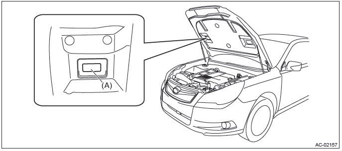
1. HFC-134A A/C SYSTEM
- The cooling system components for the HFC-134a system such as the refrigerant and compressor oil are different from the conventional CFC-12 system components and they are incompatible with each other.
- Vehicles with the HFC-134a system can be identified by the label (A) attached to the vehicle.
Before maintenance, check which A/C system is installed to the vehicle.
2. COMPRESSOR OIL
- HFC-134a compressor oil has no compatibility with that of CFC-12 system.
- Use only the manufacturer-authorized compressor oil, ND-OIL8, for the HFC-134a system.
- Do not mix multiple compressor oils.
If CFC-12 compressor oil is used in the HFC-134a A/C system, the compressor may become stuck due to poor lubrication, or the refrigerant may leak due to swelling of rubber parts.
On the other hand, if HFC-134a compressor oil is used in a CFC-12 A/C system, the durability of the A/C system will be lowered.
- HFC-134a compressor oil is very hygroscopic. When replacing or installing/removing A/C parts, immediately isolate the oil from atmosphere using a plug or tape. In order to avoid moisture, store the oil in a container with its cap tightly closed.
3. REFRIGERANT
- CFC-12 refrigerant cannot be used in a HFC-134a A/C system. HFC-134a refrigerant, also cannot be used in a CFC-12 A/C system.
- If an incorrect or no refrigerant is used, it will result in poor lubrication and the compressor itself may be damaged.
4. HANDLING OF REFRIGERANT
- The refrigerant boils at approx. -30ºC (-22ºF). When handling it, be sure to wear protective goggles and protective gloves. Direct contact of the refrigerant with skin may cause frostbite.
If the refrigerant gets into your eye, avoid rubbing your eyes with your hands. Wash your eye with plenty of water, and receive medical treatment from an eye doctor.
- Do not heat a service can. If a service can is directly heated, or put into boiling water, the inside pressure will become extremely high. This may cause the can to explode. If a service can must be warmed up, use warm water of 40ºC (104ºF) or less.
- Do not drop or impact a service can. (Observe the precautions and operation procedure described on the refrigerant can.)
- When the engine is running, do not open the high-pressure valve of manifold gauge. The high-pressure gas will back-flow resulting in an explosion of the can.
- Provide good ventilation and do not work in a closed area.
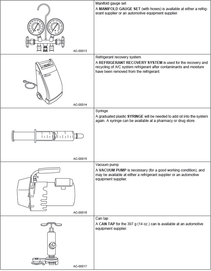
- In order to prevent global warming, avoid releasing HFC-134a into the atmosphere. Using a refrigerant recovery system, discharge and recycle the gas.
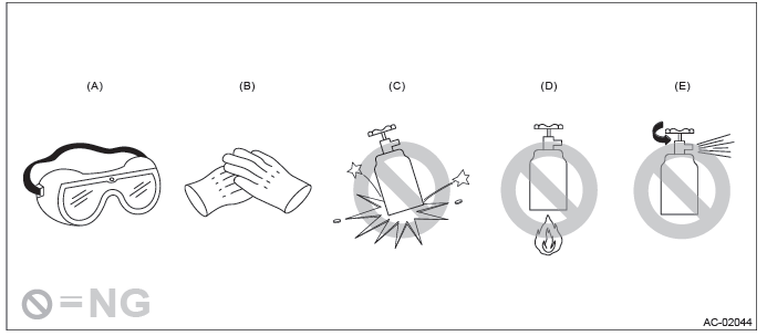
- Goggles
- Gloves
- Do not apply impact.
- No direct heat on container
- Do not discharge
5. O-RING CONNECTIONS
- Always use a new O-ring.
- In order to keep the O-rings free of lint which will cause a refrigerant gas leak, perform work without using gloves or waste cloths.
- Apply compressor oil to O-rings to avoid sticking, before installation.
- Use a torque wrench to tighten the O-ring fittings. Over-tightening will result in damage of the O-ring and deformation of the pipe end.
- If the work is interrupted before completing pipe connections, recap the pipes, components and fittings with a plug or tape to prevent foreign matter from entering.
- Visually check the surfaces and mating surfaces of O-rings, threads and connecting points. If a failure is found, replace the applicable parts.
- Install the O-rings straight against the pipe groove.
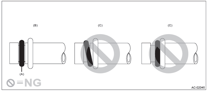
- O-ring
- OK
- NG
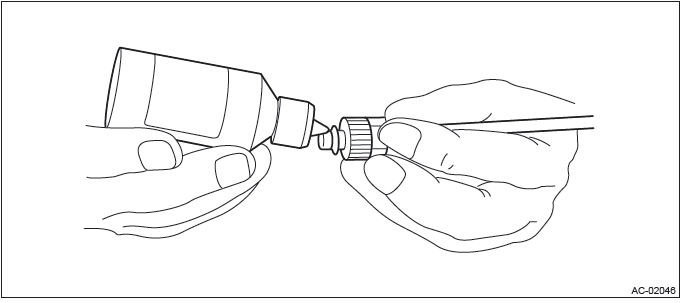
- Use compressor oil specified in the service manual to lubricate the O-rings.
Apply oil to the top and sides of O-rings before installation.
Apply compressor oil to the pipe grooves.
- After tightening, use a clean cloth to remove excess compressor oil from the connections and any oil which may have run on the vehicle body or other parts.
- If any leakage is suspected after tightening, do not tighten the connections further, but disconnect the connections, remove the O-rings, and check the O-rings, threads, and connections.
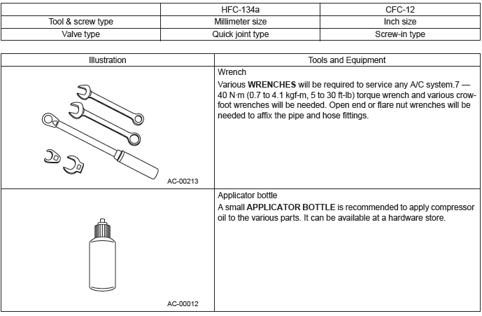
E: PREPARATION TOOL
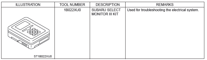
1. SPECIAL TOOL
2. GENERAL TOOL
CAUTION: When working on vehicles with a HFC-134a system, only use HFC-134a specified tools and parts. Do not mix CFC-12 tools and parts. If HFC-134a and CFC-12 refrigerant or compressor oil is mixed, it will result in poor lubrication and the compressor itself may be damaged.
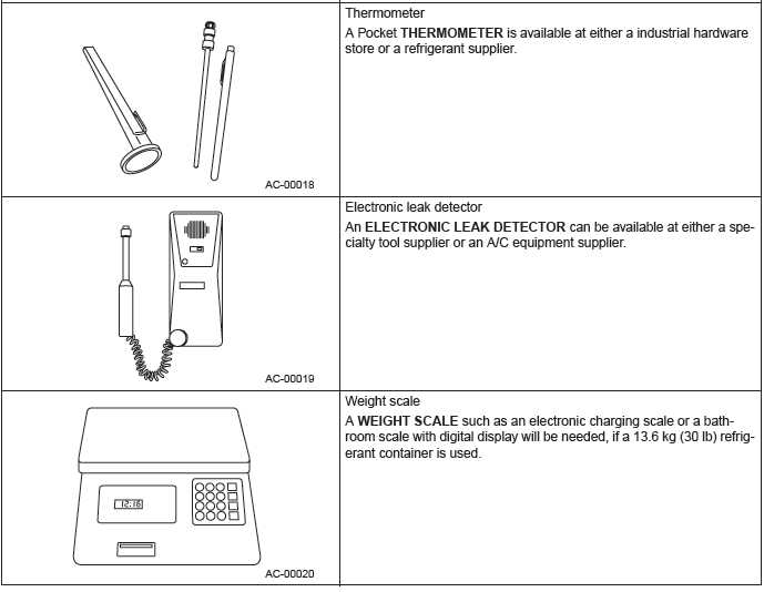
In order to prevent the mixture of HFC-134a and CFC-12 parts and liquid, the type of tool and screw, and the replacement valves used are different. The gas leak detectors for the HFC-134a and CFC-12 systems must also not be interchanged.
READ NEXT:
 Air Conditioning System
A: WIRING DIAGRAM
Refer to "Air Conditioning System" in the wiring diagram. <Ref. to WI-53,
WIRING DIAGRAM, Air Conditioning
System.>
B: ELECTRICAL SPECIFICATION
Refer to "Auto A/C Control Modu
Relay and Fuse, check fuse
A: LOCATION
NOTE: For other related fuses, refer to the wiring diagram. <Ref. to WI-15, Power Supply Circuit.>
B: INSPECTION
1. CHECK FUSE.
1) Remove the fuse and inspect visually.
2) If
Heater Core
A: REMOVAL
1) Disconnect the ground cable from battery.
2) Using the refrigerant recovery system, discharge refrigerant. <Ref. to AC-24,
PROCEDURE, Refrigerant
Recovery Procedure.>
3) Drain t
SEE MORE:
Front Bumper
A: REMOVAL
1) Disconnect the ground cable from battery.
2) Remove the front bumper face assembly.
Remove the clips, turn over the front mud guard, and disconnect the fog
light connector. (Model with
fog light)
Remove the clips at the upper side of the bumper.
Remove the clips from the fen
LOCK
The key can only be inserted or removed in this position. The ignition switch
will lock the steering wheel when you remove the key.
If turning the key is difficult, turn the steering wheel slightly to the right
and left as you turn the key.
The key can be turned from “Acc” to “LOCK”
