Subaru Outback (BR): Head restraint adjustment

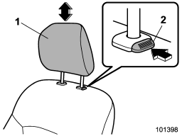
1) Head restraint
2) Release button
Both the driver’s seat and the front passenger’s seat are equipped with head restraints.
The head restraint should be adjusted so that the center of the head restraint is closest to the top of the occupant’s ears.
To raise:
Pull the head restraint up.
To lower:
Push the head restraint down while pressing the release button on the top of the
seatback.
To remove:
While pressing the release button, pull out the head restraint.
To install:
Install the head restraint into the holes that are located on the top of the seatback
until the head restraint locks.
WARNING
● Never drive the vehicle with the head restraints removed because they are designed to reduce the risk of serious neck injury in the event that the vehicle is struck from the rear. Therefore, when you remove the head restraints, you must reinstall all head restraints to protect vehicle occupants.
● All occupants, including the driver, should not operate a vehicle or sit in a vehicle’s seat until the head restraints are placed in their proper positions in order to minimize the risk of neck injury in the event of a crash.

