Subaru Outback (BR): Intake Manifold
A: REMOVAL
1. INTAKE MANIFOLD
1) Release the fuel pressure.
2) Disconnect the ground cable from battery.
3) Open the fuel filler lid and remove the fuel filler cap.
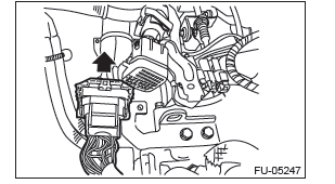
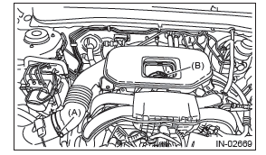
4) Remove the cover (A) and clip (B) from air intake boot assembly.
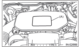
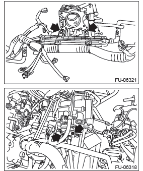
5) Loosen the clamp (A) which connects the air intake boot assembly and air cleaner case.
6) Loosen the clamp (B) which connects the air intake boot assembly and throttle body.
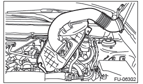
7) Remove the air intake boot from the throttle body, and move it to the left side wheel apron.
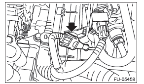
8) Disconnect the connector from the ignition coil of #3 cylinder.
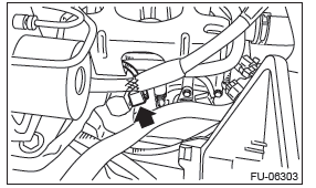
9) Remove the intake manifold protector RH.
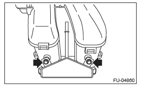
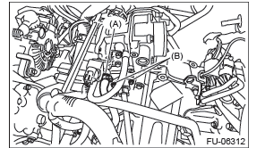
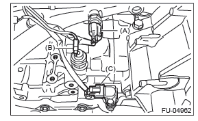
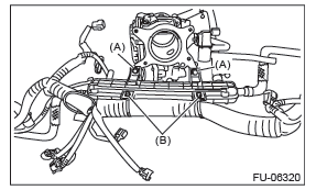
10) Remove the connector (A) from the fuel injector, and remove the fuel delivery pipe (B) from the fuel gallery RH.
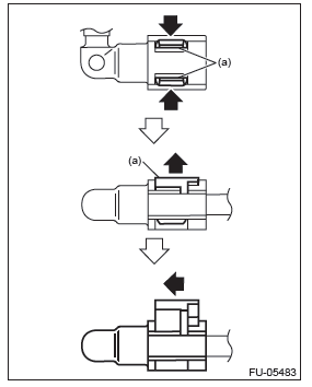
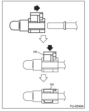
NOTE: Disconnect the quick connector as shown in the figure.
- Slider
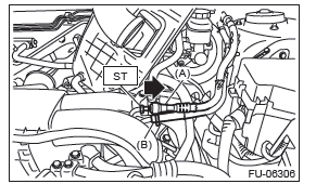
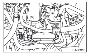
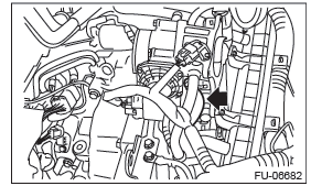
11) Disconnect the fuel delivery hose (A) and evaporation hose (B).
CAUTION:
- Be careful not to spill fuel.
- Catch the fuel from hoses using a container or cloth.
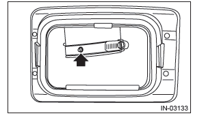
- Attach ST to the fuel delivery pipe and push ST in the direction of arrow mark to disconnect the quick connector of the fuel delivery hose (A).
ST 42099AE000 QUICK CONNECTOR RELEASE
- Remove the clip and disconnect the evaporation hose (B) from the pipe.
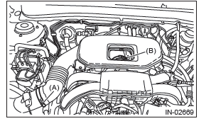
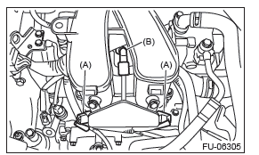
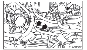
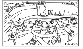
12) Remove the generator cable clip (A) from the intake manifold protector LH.
13) Remove the oil filler pipe (B) from the rocker cover LH.
14) Disconnect the brake booster vacuum hose (C).
15) Disconnect the connector from the ignition coil of #2 cylinder.
16) Remove the intake manifold protector LH.
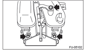
17) Remove the connector (A) from the fuel injector, and remove the fuel delivery pipe (B) from the fuel gallery LH.
NOTE: Disconnect the quick connector as shown in the figure.
- Slider
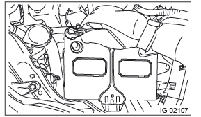
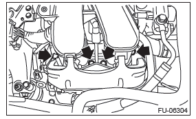
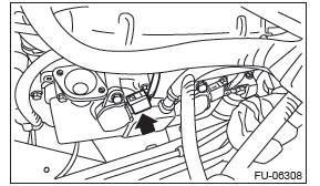
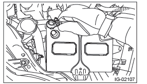
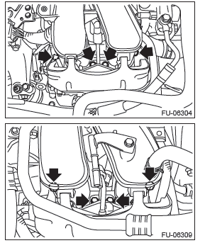
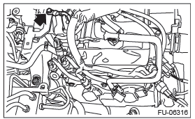
18) Remove the clip (A) securing the engine harness to the intake manifold, and remove the bolt (B) securing the LH side of the multifunction duct assembly.
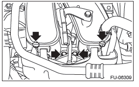
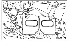
19) Remove the bolts (A) which secure the RH side of multi-function duct assembly to the intake manifold.
20) Remove the cap (B) from the intake manifold.
21) Remove the intake manifold from cylinder head.
22) Remove the fuel gallery RH and fuel injector from the intake manifold.
23) Remove the fuel gallery LH, fuel pipe and fuel injector from the intake manifold.
2. MULTI-FUNCTION DUCT ASSEMBLY
1) Release the fuel pressure.
2) Disconnect the ground cable from battery.
3) Open the fuel filler lid and remove the fuel filler cap.
4) Lift up the vehicle.
5) Remove the under cover.
6) Drain approximately 3.0
 (3.2 US qt, 2.6 Imp
qt) of coolant.
(3.2 US qt, 2.6 Imp
qt) of coolant.
7) Lower the vehicle.
8) Remove the intake manifold.
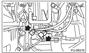
9) Remove the bolt, and disconnect the bulkhead harness connector from the engine harness connector and rear engine hanger.
10) Slide the engine harness connector in the direction of the arrow and remove it from the rear engine hanger.
11) Disconnect the connector from the knock sensor.
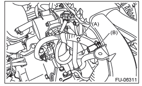
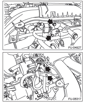
12) Disconnect the water hose (A) and EGR pipe (B) from the LH side of multi-function duct assembly.
13) Disconnect the water hose from the RH side of multi-function duct assembly.
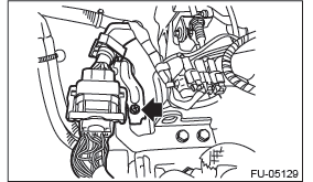
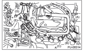
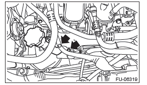
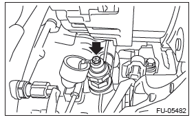
14) Disconnect the connector (A) from the engine coolant temperature sensor, and disconnect the terminal (B) from oil pressure switch and the connector (C) from the crankshaft position sensor.
15) Disconnect the connector (A) from front oxygen (A/F) sensor and the connector (B) from the rear oxygen sensor.
16) Disconnect the connector (C) from the ignition coil of #1 cylinder.
17) Disconnect the connector (D) from the oil switching solenoid valve RH, disconnect the connector (E) from the oil temperature sensor RH, disconnect the connector (F) from the variable valve lift diagnosis switch and disconnect the ground terminal (G) from the rear engine hanger.
18) Slide the front oxygen (A/F) sensor connector and rear oxygen sensor connector in the direction of the arrow and remove them from the bracket.
19) Disconnect the connector from the ignition coil of #4 cylinder.
20) Disconnect the connector (A) from the oil switching solenoid valve LH and the connector (B) from the camshaft position sensor LH.
21) Remove the bolt (A) securing the multi-function duct assembly to the PCV pipe, and remove the multi-function duct assembly.
22) Remove the clip (B) securing the engine harness to the PCV pipe, and remove the engine harness.
B: INSTALLATION
1. INTAKE MANIFOLD
Install in the reverse order of removal while being careful of the following.
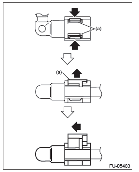
- Connect the quick connector as shown in the figure.
CAUTION:
- Check that there is no damage or dust on the quick connector. If necessary, clean the seal surface of the pipe.
- When connecting the quick connector, make sure to insert the pipe all the way in before locking the slider.
- When it is difficult to lock the slider, check that the pipe is fully inserted.
- Make sure that the quick connector is securely connected.
NOTE:
- Use a new gasket.
- If fuel hoses or clamps are damaged, replace them with new parts.
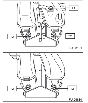
Tightening torque:
T1: 6.4 N*m (0.7 kgf-m, 4.7 ft-lb)
T2: 19 N*m (1.9 kgf-m, 14.0 ft-lb)
Tightening torque: 6.4 N*m (0.7 kgf-m, 4.7 ft-lb)
Tightening torque: 25 N*m (2.5 kgf-m, 18.4 ft-lb)
Tightening torque: 6.4 N*m (0.7 kgf-m, 4.7 ft-lb)
NOTE: Align the clamp hole with the protrusion of the air intake boot assembly.
Tightening torque:
Clamp (A), (B)
3 N*m (0.3 kgf-m, 2.2 ft-lb)
2. MULTI-FUNCTION DUCT ASSEMBLY
Install in the reverse order of removal.
NOTE:
- Use a new gasket.
- The oil pressure switch harness must be positioned to be within the range of a 45º angle on either left or right toward the rear of the vehicle.
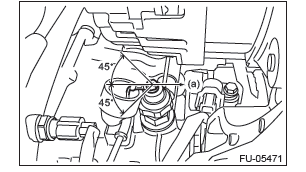
- Front side of vehicle
Tightening torque: 1.5 N*m (0.2 kgf-m, 1.1 ft-lb)
Tightening torque: 6.4 N*m (0.7 kgf-m, 4.7 ft-lb)
Tightening torque: 19 N*m (1.9 kgf-m, 14.0 ft-lb)
C: INSPECTION
1) Check that the intake manifold and fuel pipe have no deformation, cracks and other damages.
2) Check that the hose has no cracks, damage or loose part.
Engine Coolant Temperature Sensor
A: REMOVAL
1) Disconnect the ground cable from battery.
2) Remove the generator.
3) Drain engine coolant.
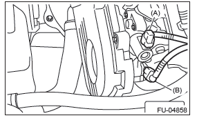
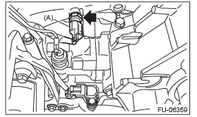
4) Disconnect the connector (A) from the engine coolant temperature sensor, and remove the engine coolant temperature sensor.
B: INSTALLATION
Install in the reverse order of removal.
NOTE: Use a new gasket.
Tightening torque: 18 N*m (1.8 kgf-m, 13.3 ft-lb)
C: INSPECTION
1) Check that the engine coolant temperature sensor has no deformation, cracks or other damages.
2) Immerse the engine coolant temperature sensor and a thermometer in water.
CAUTION: Take care not to allow water to get into the engine coolant temperature sensor connector.
Completely remove any water inside.
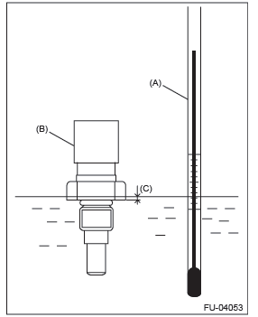
- Thermometer
- Engine coolant temperature sensor
- Hexagonal part height: To approx.1/3
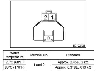
3) Raise water temperature gradually, measure the resistance between the engine coolant temperature sensor terminals when the temperature is 20ºC (68ºF) and 80ºC (176ºF).
NOTE: Agitate the water for even temperature distribution.
READ NEXT:
 Crankshaft Position Sensor
A: REMOVAL
1) Disconnect the ground cable from battery.
2) Remove the bolt which secures crankshaft position
sensor to oil pump.
3) Remove the crankshaft position sensor, and disconnect
the connecto
Knock Sensor
A: REMOVAL
1) Disconnect the ground cable from battery.
2) Remove the cover (A) and clip (B) from air intake
boot assembly.
3) Loosen the clamp (A) which connects the air intake
boot assembly and ai
Manifold Absolute Pressure
Sensor
A: REMOVAL
1) Disconnect the ground cable from battery.
2) Remove the cover (A) and clip (B) from air intake
boot assembly.
3) Loosen the clamp (A) which connects the air intake
boot assembly and ai
SEE MORE:
Light control switch
The light control switch only operates when the key is inserted into the ignition
switch.
Regardless of the position of the light control switch, the illuminated lights
are turned off when the key is removed from the ignition switch.
NOTE
● Even if the key is removed from the ignition s
High/low beam change (dimmer)
To change from low beam to high beam, push the turn signal lever forward. When
the headlights are on high beam, the high beam indicator light “”
on the combination meter is also on.
To switch back to low beam, pull the lever back to the detent position.
