Subaru Outback (BR): Pressure Sensor
A: INSPECTION
1) Perform a diagnosis code (DTC) check by connecting the Subaru Select Monitor.
2) If any diagnosis code (DTC) is displayed, refer to "List of Diagnostic Trouble Code (DTC)" in "HVAC SYSTEM (DIAGNOSTICS)" section. <Ref. to AC(diag)-53, LIST, List of Diagnostic Trouble Code (DTC).>
Ambient Sensor (Auto A/C Model)
A: REMOVAL
1) Disconnect the ground cable from battery.
2) Remove the clips and remove the grille bracket. (Sedan model)
NOTE: To prevent damage to the grille bracket, make sure to remove all clips.
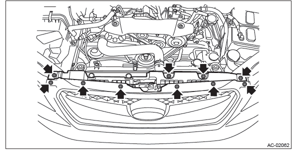
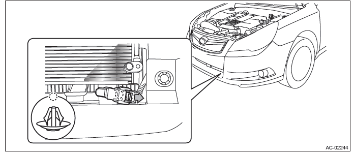
3) Remove the ambient sensor.
- Disconnect the connector.
- Remove the ambient sensor from the radiator lower panel.
B: INSTALLATION
Install each part in the reverse order of removal.
C: INSPECTION
Preparation tool: Circuit tester
1) Visually check the ambient sensor for dirt or damage, and clean or replace as necessary.
2) Check the resistance between ambient sensor terminals.
CAUTION: During inspection, be careful not to touch the sensor end in order to avoid misjudgment due to body temperature.
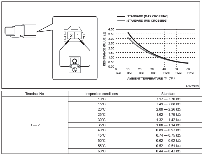
3) Replace the ambient sensor if the inspection result is not within the standard value.
Sunload Sensor (Auto A/C Model)
A: REMOVAL
NOTE: The sunload sensor is integrated with the light control sensor.
1) Disconnect the ground cable from battery.
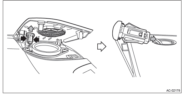
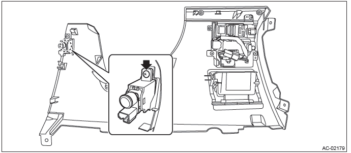
2) Remove the sunload sensor.
CAUTION: Be careful not to damage the sensors and interior trims when removing.
- Release the claws and clips, then detach the side speaker cover (RH).
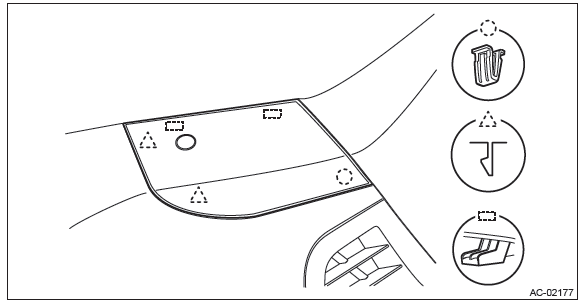
- Push out the sunload sensor by pressing the left and right claws.
- Disconnect the connector and remove the sunload sensor.
B: INSTALLATION
Install each part in the reverse order of removal.
C: INSPECTION
Preparation tool: Subaru Select Monitor III KIT
1) Check if there is anything that affects sensing, around the sunload sensor.
- Is there anything placed on the sunload sensor that disturbs sensing?
- Is there anything on the windshield glass, such as sticker and film, that disturbs sensing?
- No → Go to step 2).
- Yes → Remove everything that affects sensing.
2) Check the sunload sensor using the Subaru Select Monitor.
- Prepare the Subaru Select Monitor kit.
- Run the "PC application for Subaru Select Monitor".
- On "Main Menu" display, select {Each System Check}.
- On "System Selection Menu" display, select {Air Condition System}.
- On "Air Conditioning Diagnosis" display, select {Current Data Display & Save}.
- Select {Quantity of Sunload} with UP/DOWN key and set with the [OK] key.
- Cover the sunload sensor with cloth and the like to avoid direct light. Does {Quantity of Sunload} indicate 0 W/m2?
- Yes → Go to step 3).
- No → Replace the sunload sensor.
3) From step 2), expose the sunload sensor to light.
- Place intense light such as incandescent light at 30 cm or less from the sunload sensor.
- Does the {Quantity of Sunload} indicate 2000 W/m2 or less?
CAUTION: The value changes depending on the angle of light.
- Yes → The sunload sensor is normal.
- No → Replace the sunload sensor.
In-Vehicle Sensor (Auto A/C Model)
A: REMOVAL
CAUTION: Be careful not to damage the sensors and interior trims when removing.
1) Disconnect the ground cable from battery.
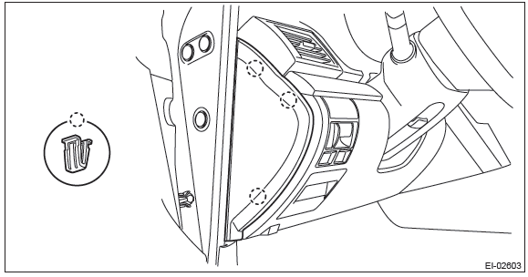
2) Remove the clips, and remove the instrument panel side cover LH.
3) Remove the instrument panel lower cover.
- Remove the clip.
- Remove the data link connector, and remove the instrument panel lower cover under.
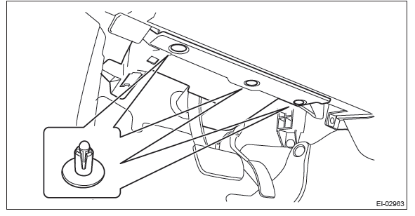
- Remove the screws and clips and release the claws, and remove the instrument panel lower cover while disconnecting the harness connectors.
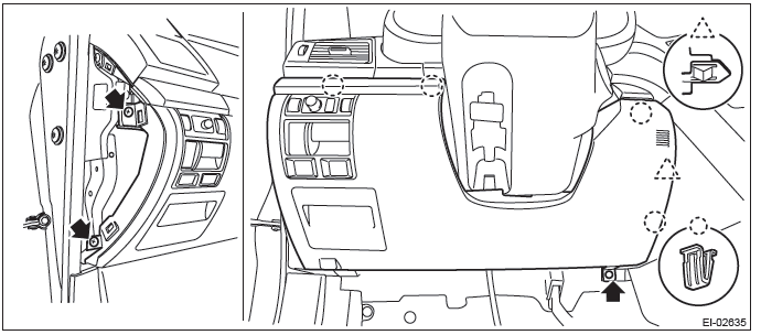
4) Remove the screw and remove the in-vehicle sensor from the instrument lower cover.
B: INSTALLATION
Install each part in the reverse order of removal.
C: INSPECTION
Preparation tool: Circuit tester
1) Set the vehicle to the following conditions.

2) Check the suction port (A) for in-vehicle sensor provided on the instrument panel lower cover.
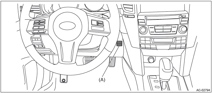
- Put a strip of paper close to the front side of the suction port (A).
- Can you see the paper moving towards the port and the air being sucked into the port?
CAUTION: Be careful not to let the paper get sucked into the port.
- Yes → Go to step 5).
- No → Go to step 3).
3) Remove the instrument panel lower cover, and check the aspirator hose (A).
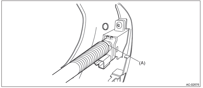
- Is the aspirator hose on both sides of case and sensor disconnected?
- Are there any kinks or cracks on the aspirator hose?
- No → Go to step 4).
- Yes → Repair or replace the aspirator hose if necessary.
4) Check if there is anything that affects sensing, around the in-vehicle sensor.
- Is the in-vehicle sensor hole plugged?
- Is there any heat-producing part (audio or navigation system, etc.) around in-vehicle sensor?
- No → Go to step 5).
- Yes → Remove everything that affects sensing.
5) Perform the inspection of in-vehicle sensor unit.
- Disconnect the in-vehicle sensor connector.
- Is the resistance between terminals of in-vehicle sensor within standard value?
CAUTION: During inspection, be careful not to touch the sensor end in order to avoid misjudgment due to body temperature.
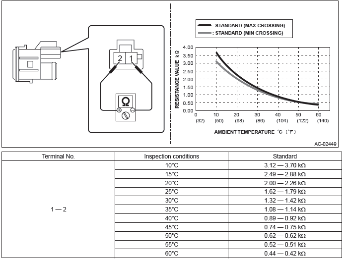
- Yes → The in-vehicle sensor is normal.
- No → Replace the in-vehicle sensor.
Evaporator Sensor
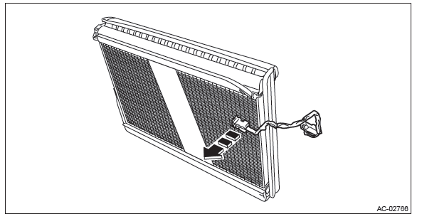
A: REMOVAL
1) Remove the evaporator. <Ref. to AC-66, REMOVAL, Evaporator.>
2) Remove the evaporator sensor from the evaporator.
B: INSTALLATION
CAUTION:
- Do not start the engine before charging refrigerant.
- If the engine is started with no refrigerant charge, replace the compressor.
- Make sure that the water seal gasket on the cover attachment area is securely attached.
- Replace the O-rings with new parts, and then apply compressor oil.
1) Install the evaporator sensor at the position shown in the figure below.
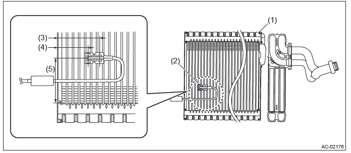
- Evaporator
- Evaporator sensor
- 47.7 mm (1.88 in)
- 34.3 mm (1.35 in)
- 50 mm (1.97 in)
2) Install each part in the reverse order of removal.
NOTE: Refer to "INSTALLATION" of "Instrument Panel Assembly". <Ref. to EI-95, INSTALLATION, Instrument Panel Assembly.>
3) Fill engine coolant.
- H4 non-turbo model: <Ref. to CO(H4SO)-14, FILLING OF ENGINE COOLANT, REPLACEMENT, Engine Coolant.>
- H4 turbo model: <Ref. to CO(H4DOTC)-14, FILLING OF ENGINE COOLANT, REPLACEMENT, Engine Coolant.>
- H6 model: <Ref. to CO(H6DO)-12, FILLING OF ENGINE COOLANT, REPLACEMENT, Engine Coolant.>
4) Charge refrigerant. <Ref. to AC-25, PROCEDURE, Refrigerant Charging Procedure.>
Tightening torque:
Heater cooling unit: <Ref. to AC-6, HEATER COOLING UNIT, COMPONENT, General
Description.>
Blower motor unit: <Ref. to AC-8, BLOWER MOTOR UNIT, COMPONENT, General
Description.>
C: INSPECTION
Preparation tool:
Subaru Select Monitor III KIT
Circuit tester
Thermometer
1) Prepare the vehicle.
NOTE: Check that the ambient temperature is 25 - 40ºC (77 - 104ºF) and that the humidity is 30% - 80%.
- Place the vehicle in the workshop or in the shade and windless condition.
- Open all windows.
2) Set the vehicle to the following conditions.
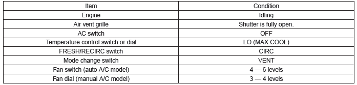
3) Using the Subaru Select Monitor, check the evaporator sensor.
- Prepare the Subaru Select Monitor kit.
- Run the "PC application for Subaru Select Monitor".
- On "Main Menu" display, select {Each System Check}.
- On "System Selection Menu" display, select {Air Condition System}.
- On "Air Conditioning Diagnosis" display, select {Current Data Display & Save}.
- Select {Evaporator Temperature} with UP/DOWN key and set with the [OK] key.
- Idle the engine for 15 minutes, and then compare the outlet opening temperature with {Evaporator Temperature Target}.
NOTE: For outlet opening temperature, measure the average temperature of center grille assembly and side grille assembly.
- Is the difference between outlet opening temperature and {Evaporator Temperature Target} by 3ºC (5.4ºF) or more?
- Yes → Go to step 4).
- No → Evaporator sensor is normal.
4) Perform the inspection of evaporator sensor unit.
- Disconnect the evaporator sensor connector.
- Is the resistance between terminals of evaporator sensor within standard value?
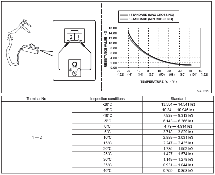
- Yes → Evaporator sensor is normal.
- No → Replace the evaporator sensor.
READ NEXT:
 FRESH/RECIRC Door Actuator
A: REMOVAL
1) Set the intake door actuator to RECIRC position.
Turn the ignition switch to ON.
Operate the control panel and switch to RECIRC mode.
In the condition of step (2), turn the ignition
Air Mix Door Actuator
A: REMOVAL
1. DRIVER'S SEAT
1) Remove the instrument panel lower cover. <Ref. to EI-64, REMOVAL,
Instrument Panel Lower Cover.>
2) Remove the bolts, and remove the knee guard panel.
3) Remove
Heater Duct
A: REMOVAL
1) Remove the front seats. <Ref. to SE-10, REMOVAL, Front Seat.>
2) Remove the instrument panel face assembly. <Ref. to EI-76, REMOVAL,
Instrument Panel Assembly.>
3) Remove
SEE MORE:
Temporary spare tire
WARNING
● Never tow a trailer when the temporary spare tire is used. The temporary spare
tire is not designed to sustain the towing load. Use of the temporary spare tire
when towing can result in failure of the spare tire and/or less stability of the
vehicle and may lead to an accident.
How to jump start
1. Make sure the booster battery is 12 volts and the negative terminal is grounded.
2. If the booster battery is in another vehicle, do not let the two vehicles
touch.
3. Turn off all unnecessary lights and accessories.
4. Connect the jumper cables exactly in the sequence illustrated.
1) Con
