Subaru Outback (BR): Throttle Body
A: REMOVAL
1) Disconnect the ground cable from battery.
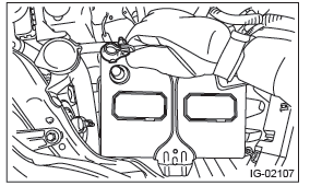
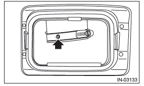
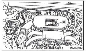
2) Remove the cover (A) and clip (B) from air intake boot assembly.
3) Loosen the clamp (A) which connects the air intake boot assembly and air cleaner case.
4) Loosen the clamp (B) which connects the air intake boot assembly and throttle body.
5) Remove the air intake boot from the throttle body, and move it to the left side wheel apron.
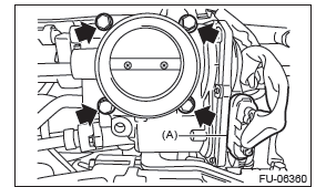
6) Disconnect the connectors (A) from the throttle position sensor.
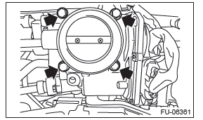
7) Remove the bolts which secure the throttle body to the multi-function duct assembly, and remove the throttle body.
B: INSTALLATION
Install in the reverse order of removal.
NOTE: Use a new gasket.
Tightening torque: 8 N*m (0.8 kgf-m, 5.9 ft-lb)
NOTE: Align the clamp hole with the protrusion of the air intake boot assembly.
Tightening torque:
Clamp (A), (B)
3 N*m (0.3 kgf-m, 2.2 ft-lb)
C: INSPECTION
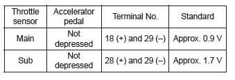
1. THROTTLE SENSOR (METHOD WITH CIRCUIT TESTER)
1) Warm up the engine.
2) Remove the glove box lid assembly.
3) Turn the ignition switch to ON. (engine OFF)
4) Measure the voltage between ECM connector terminals.
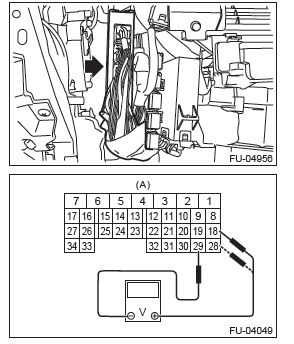
- To ECM connector
5) After inspection, install the related parts in the reverse order of removal.
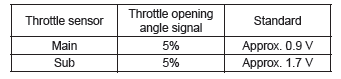
2. THROTTLE SENSOR (METHOD WITH SUBARU SELECT MONITOR)
1) Warm up the engine.
2) Turn the ignition switch to ON. (engine OFF)
3) Read the throttle opening angle signal and voltage of throttle sensor using Subaru Select Monitor.
3. OTHER INSPECTIONS
1) Check that the throttle body has no deformation, cracks or other damages.
2) Check that the engine coolant hose has no cracks, damage or loose part.
READ NEXT:
 Intake Manifold
A: REMOVAL
1. INTAKE MANIFOLD
1) Release the fuel pressure.
2) Disconnect the ground cable from battery.
3) Open the fuel filler lid and remove the fuel filler
cap.
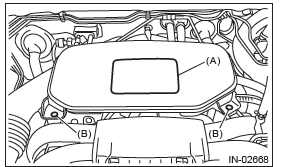
4) Remove the cover (A) and clip
Crankshaft Position Sensor
A: REMOVAL
1) Disconnect the ground cable from battery.
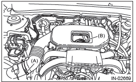
2) Remove the bolt which secures crankshaft position
sensor to oil pump.
3) Remove the crankshaft position sensor, and disconnect
the connecto
Knock Sensor
A: REMOVAL
1) Disconnect the ground cable from battery.
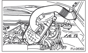
2) Remove the cover (A) and clip (B) from air intake
boot assembly.
3) Loosen the clamp (A) which connects the air intake
boot assembly and ai
SEE MORE:
Hill Holder indicator light
WARNING
If the Hill Holder indicator light does not illuminate even when the Hill Holder
switch is pressed to activate the Hill Holder function, the electronic parking brake
system may be malfunctioning. Immediately stop the vehicle in a safe location and
contact your SUBARU dealer.
The li
Rear Differential Front Oil
Seal
A: INSPECTION
Make sure that there is no leakage from front oil
seal portion. If there is any leakage, replace the oil
seal and inspect the propeller shaft.
B: REPLACEMENT
1) Shift the select lever or gear shift lever to neutral.
2) Release the parking brake.
3) Disconnect the ground cable from ba
