Subaru Outback (BR): VDC Control Module and Hydraulic Control Unit (VDCCM&H/U)
A: REMOVAL
1) Disconnect the ground cable from battery.
2) Remove the air intake boot.
- H4 model: <Ref. to IN(H4DOTC)-10, REMOVAL, Air Intake Boot.>
- H6 model: <Ref. to IN(H6DO)-7, REMOVAL, Air Intake Boot.>
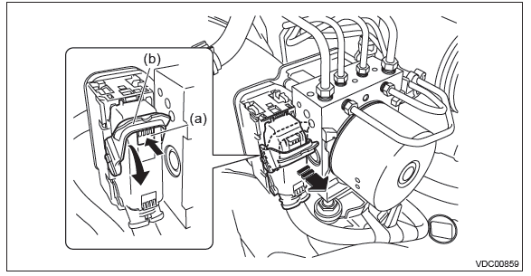
3) Remove the VDC control module & hydraulic control unit (VDCCM&H/U).
- Remove any dirt from around the VDCCM&H/U.
- Push the lock button (a), pull down the lock lever (b) and disconnect the VDCCM&H/U connector.
CAUTION: Do not pull on the harness when disconnecting the connector.
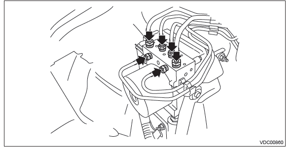
- Using a flare nut wrench, disconnect each brake pipe from VDCCM&H/U.
CAUTION:
- Wrap the brake pipe with a vinyl bag so as not to spill the brake fluid on the painted surface of the vehicle body.
- If brake fluid is spilled on the painted surface of the vehicle body, wash it off immediately with water and wipe clean.
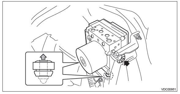
- Remove the bolt, and then remove the VDCCM&H/U from the bracket damper.
CAUTION:
- Do not drop or bump the VDCCM&H/U.
- Do not turn the VDCCM&H/U upside down or place it sideways for storage.
- Be careful not to let foreign matter enter the VDCCM&H/U.
- Be careful that no water enters the connectors.
B: INSTALLATION
CAUTION:
- When installing the VDCCM&H/U to the bracket, make sure that there is no oil adhered to the threads of VDCCM&H/U. If the oil is adhered, degrease it carefully before tightening.
- Connect the VDCCM&H/U connector securely.
1) Install each part in the reverse order of removal.
Tightening torque: Refer to "COMPONENT" of "General Description". <Ref. to VDC-5, VDC CONTROL MODULE & HYDRAULIC CONTROL UNIT (VDCCM&H/U), COMPONENT, General Description.>
2) Bleed air from the brake system. <Ref. to BR-54, Air Bleeding.>
3) Perform parameter confirmation, selection, and registration.
NOTE:
- When the VDCCM&H/U is replaced with a new part, be sure to perform the selection registration operation.
- For the selection and registration of parameter, the Subaru Select Monitor is required.
- When the registration has not been performed, the DTC code "Parameter selection error" is detected together with the ABS/EBD/VDC warning light illumination.
- Check that the applied model and grade of the relevant vehicle are included. <Ref. to VDC(diag)-19, PARAMETER CHECK, OPERATION, Subaru Select Monitor.>
- If the applied model and grade of the target vehicle are not included on the {Confirm on parameter} display screen, perform parameter selection and registration. <Ref. to VDC(diag)-19, PARAMETER SELECTION, OPERATION, Subaru Select Monitor.>
4) Perform mode setting for each sensor.
- Set up mode for Neutral of Steering Angle Sensor & Lateral G Sensor 0 point: <Ref. to VDC-16, SET UP MODE FOR NEUTRAL OF STEERING ANGLE SENSOR & LATERAL G SENSOR 0 POINT, ADJUSTMENT, VDC Control Module and Hydraulic Control Unit (VDCCM&H/U).>
- Longitudinal G sensor & lateral G sensor 0 point setting mode: <Ref. to VDC-16, LONGITUDINAL G SENSOR & LATERAL G SENSOR 0 POINT SETTING MODE, ADJUSTMENT, VDC Control Module and Hydraulic Control Unit (VDCCM&H/U).>
C: INSPECTION
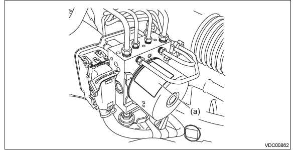
1) Check the identification label (a) of the VDC control unit & hydraulic control unit (VDCCM&H/U).
NOTE: For the identification label, refer to "SPECIFICATION" in "General Description". <Ref. to VDC-2, SPECIFICATION, General Description.>
2) Check the condition of connection and settlement of connector, and correct or replace if defective.
1. CHECKING THE HYDRAULIC UNIT ABS OPERATION BY PRESSURE GAUGE
1) Lift up the vehicle, and then remove the wheel.
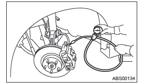
2) Remove the air bleeder screws from FL and FR caliper bodies.
3) Connect two pressure gauges to FL and FR caliper bodies.
CAUTION:
- Use a pressure gauge used exclusively for brake fluid measurement.
- Do not use the pressure gauge used for the measurement of transmission oil. Doing so will cause the piston seal to expand and deform.
NOTE: Wrap sealing tape around the pressure gauge.
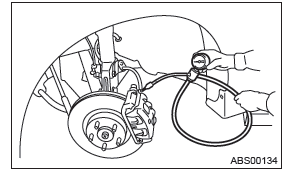
4) Bleed air from the pressure gauges and the FL and FR caliper bodies.
5) Perform ABS sequence control. <Ref. to VDC-17, ABS Sequence Control.>
6) When the hydraulic unit begins to work, first the FL side performs decompression, hold and compression, and then the FR side performs decompression, hold and compression.
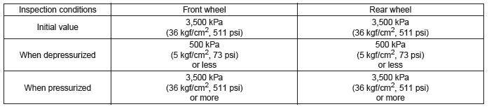
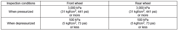
7) Read values indicated on the pressure gauge and check if the fluctuation of the values between decompression and compression meets the standard values. Depress the brake pedal and check that the kick-back is normal, and tightness is normal.
8) Disconnect the pressure gauges from FL and FR caliper bodies.
9) Install the air bleeder screws of FL and FR caliper bodies.
10) Remove the air bleeder screws from RL and RR caliper bodies.
11) Connect two pressure gauges to RL and RR caliper bodies.
12) Bleed air from RL and RR caliper bodies, and pressure gauge.
13) Perform ABS sequence control. <Ref. to VDC-17, ABS Sequence Control.>
14) When the hydraulic unit begins to work, first the RR side performs decompression, hold and compression, and then the RL side performs decompression, hold and compression.
15) Read values indicated on the pressure gauge and check if the fluctuation of the values between decompression and compression meets specification. Depress the brake pedal and check that the kick-back is normal, and tightness is normal.
16) Disconnect the pressure gauge from the RL and RR caliper bodies.
17) Install the air bleeder screws of RL and RR caliper bodies.
18) Bleed air from the brake system. <Ref. to BR-54, Air Bleeding.>
2. CHECKING THE HYDRAULIC UNIT ABS OPERATION WITH THE BRAKE TESTER
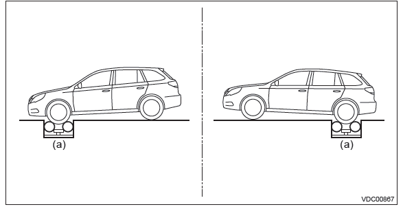
1) Set wheels other than the one to measure on free rollers.
2) Prepare for the ABS sequence control operation. <Ref. to VDC-17, ABS Sequence Control.>
3) Set the front wheels or rear wheels on the brake tester (a) and set the gear to neutral.
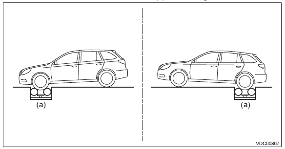
4) Operate the brake tester.
5) Perform ABS sequence control. <Ref. to VDC-17, ABS Sequence Control.>
6) When the hydraulic unit begins to work, check the following work sequence.
- The FL wheel performs decompression, hold and compression in sequence, and subsequently the FR wheel repeats the cycle.
- The RR wheel performs decompression, hold and compression in sequence, and subsequently the RL wheel repeats the cycle.
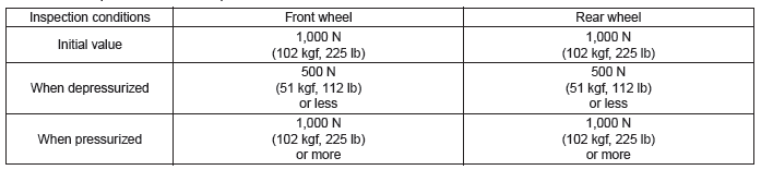
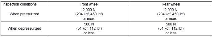
7) Read values indicated on the brake tester and check if the fluctuation of the values between decompression and compression meets specification.
8) After the inspection, depress the brake pedal and check that it is not abnormally hard, and tightness is normal.
3. CHECKING THE HYDRAULIC UNIT VDC OPERATION USING A PRESSURE GAUGE
1) Lift up the vehicle, and then remove the wheel.
2) Remove the air bleeder screws from FL and FR caliper bodies.
3) Connect two pressure gauges to FL and FR caliper bodies.
CAUTION:
- Use a pressure gauge used exclusively for brake fluid measurement.
- Do not use a pressure gauge used for the measuring transmission oil pressure, as the piston seal may expand and deform.
NOTE: Wrap sealing tape around the pressure gauge.
4) Bleed air from the pressure gauge.
5) Perform VDC sequence control. <Ref. to VDC-20, VDC Sequence Control.>
6) When the hydraulic unit begins to work, first the FL side performs compression, hold, and decompression, and then the FR side performs compression, hold, and decompression.
7) Read values indicated on the pressure gauge and check if the fluctuation of the values between decompression and compression meets specification. Depress the brake pedal and check that it is not abnormally hard, and tightness is normal.
8) Disconnect the pressure gauges from FL and FR caliper bodies.
9) Install the air bleeder screws of FL and FR caliper bodies.
10) Remove the air bleeder screws from RL and RR caliper bodies.
11) Connect two pressure gauges to RL and RR caliper bodies.
12) Bleed air from RL and RR caliper bodies, and pressure gauge.
13) Perform VDC sequence control. <Ref. to VDC-20, VDC Sequence Control.>
14) When the hydraulic unit begins to work, first the RR side performs compression, hold, and decompression, and then the RL side performs compression, hold, and decompression.
15) Read the values indicated on the pressure gauges and check if it is within specification. Depress the brake pedal and check that it is not abnormally hard, and tightness is normal.
16) Disconnect the pressure gauge from the RL and RR caliper bodies.
17) Install the air bleeder screws of RL and RR caliper bodies.
18) Bleed air from the brake system. <Ref. to BR-54, Air Bleeding.>
4. CHECK HYDRAULIC UNIT VDC OPERATION WITH BRAKE TESTER
1) Set wheels other than the one to measure on free rollers.
2) Prepare to operate the VDC sequence control. <Ref. to VDC-20, VDC Sequence Control.>
3) Set the front wheels or rear wheels on the brake tester (a) and set the gear to neutral.
4) Operate the brake tester.
5) Perform VDC sequence control. <Ref. to VDC-20, VDC Sequence Control.>
6) When the hydraulic unit begins to work, check the following work sequence.
- The FL wheel performs compression, hold and decompression in sequence, and subsequently the FR wheel repeats the cycle.
- The RR wheel performs compression, hold and decompression in sequence, and subsequently the RL wheel repeats the cycle.
7) Read values indicated on the brake tester and check if the fluctuation of the values between decompression and compression meets specification.
8) After the inspection, depress the brake pedal and check that it is not abnormally hard, and tightness is normal.
D: ADJUSTMENT
1. SET UP MODE FOR NEUTRAL OF STEERING ANGLE SENSOR & LATERAL G SENSOR 0 POINT
After installing, replacing, or adjusting the following part, perform the Set up mode for Neutral of Steering Angle Sensor & Lateral G Sensor 0 point.
- Steering angle sensor
- Steering wheel
- Suspension parts
- Wheel alignment
- VDCCM&H/U
- VDCCM&H/U bracket
1) Set the steering wheel to the neutral position.
2) Connect the Subaru Select Monitor to data link connector.
- Run the "PC application for Subaru Select Monitor".
- On "Main Menu" display, select {Each System Check}.
- Select {Brake Control System}. When {VDC} is displayed, select the [OK] button.
- From {Current Data Display & Save}, select {Steer Angle Sensor Op}.
3) Check that the steering angle sensor output value is between -10 and 10 deg.
4) From {Function Check Sequence}, select {Set up mode for Neutral of Steering Angle Sensor & Lateral G Sensor 0 point}, and perform the setting according to the procedure displayed on the Subaru Select Monitor Screen.
5) Drive the vehicle for 10 minutes, and check that there is no system malfunction or the warning light illumination while driving.
6) Make sure that the DTC is not stored.
2. LONGITUDINAL G SENSOR & LATERAL G SENSOR 0 POINT SETTING MODE
After installing or replacing the following part, perform the longitudinal G sensor & lateral G sensor 0 point setting mode.
- Suspension parts
- VDCCM&H/U
- VDCCM&H/U bracket
1) Park the vehicle on a level surface with all wheels aligned straight.
2) Connect the Subaru Select Monitor to data link connector.
- Run the "PC application for Subaru Select Monitor".
- On "Main Menu" display, select {Each System Check}.
- Select {Brake Control System}. When {VDC} is displayed, select the [OK] button.
- From {Current Data Display & Save}, select {Longitudinal G Sensor Output} and {Lateral G Sensor Output}.
3) Check that output values for the longitudinal G sensor and lateral G sensor are -2 - 2 m/s2.
4) From {Function Check Sequence}, select {Longitudinal G Sensor & Lateral G Sensor 0 Point Setting Mode}, and perform the setting according to the procedure displayed on the Subaru Select Monitor Screen.
5) Drive the vehicle for 10 minutes, and check that there is no system malfunction or the warning light illumination while driving.
6) Make sure that the DTC is not stored.
READ NEXT:
 ABS Sequence Control
A: OPERATION
1) While the ABS sequence control is being performed, the operation of the
hydraulic unit can be checked using
the brake tester or pressure gauge after the hydraulic unit solenoid valve
Yaw Rate and G Sensor
A: NOTE
Yaw rate & longitudinal G and lateral G sensor are integrated with the VDC
control module & hydraulic control
module (VDCCM&H/U).
B: INSPECTION
1. YAW RATE & LONGITUDINAL G AN
Front ABS Wheel Speed Sensor
A: REMOVAL
1) Disconnect the ground cable from battery.
2) Lift up the vehicle, and then remove the front wheels.
3) Remove the front ABS wheel speed sensor.
CAUTION:
Be careful not to damage the
SEE MORE:
Immobilizer (Diagnostics)
Basic Diagnostic Procedure
A: PROCEDURE
General Description
A: CAUTION
CAUTION:
Do not use electrical test devices on any airbag
system wiring harnesses and connector
circuits.
Be careful not to damage the airbag system
wiring harness.
While diagnostic items are being checked, do
not opera
Oil Charge Pipe
A: REMOVAL
1) Disconnect the ground cable from battery.
2) Lift up the vehicle.
3) Remove the under cover. <Ref. to EI-35, REMOVAL,
Front Under Cover.>
4) Remove the front exhaust pipe. <Ref. to
EX(H6DO)-5, REMOVAL, Front Exhaust Pipe.>
5) Disconnect the connector from turbine speed
