Subaru Outback (BR): Converter Case Cover
A: REMOVAL
1) Remove the transmission assembly from the vehicle. <Ref. to CVT-55, REMOVAL, Automatic Transmission Assembly.>
2) Remove the air breather hose. <Ref. to CVT-132, REMOVAL, Air Breather Hose.>
3) Remove the oil pan and control valve body. <Ref. to CVT-111, REMOVAL, Control Valve Body.>
4) Remove the transmission harness. <Ref. to CVT-121, REMOVAL, Transmission Harness.>
5) Remove the extension case. <Ref. to CVT-138, REMOVAL, Extension Case.>
6) Remove the rear drive shaft. <Ref. to CVT-141, REMOVAL, Rear Drive Shaft.>
7) Remove the transfer clutch assembly. <Ref. to CVT-146, REMOVAL, Transfer Clutch.>
8) Remove the transfer reduction driven gear assembly. <Ref. to CVT-158, REMOVAL, Transfer Reduction Driven Gear.>
9) Remove the intermediate case. <Ref. to CVT-165, REMOVAL, Intermediate Case.>
10) Remove the forward clutch assembly. <Ref. to CVT-180, REMOVAL, Forward Clutch Assembly.>
11) Remove the transmission case. <Ref. to CVT-211, REMOVAL, Transmission Case.>
12) Remove the primary pulley, secondary pulley and variator chain. <Ref. to CVT-226, REMOVAL, Primary Pulley and Secondary Pulley.>
13) Remove the drive pinion shaft assembly. <Ref. to CVT-242, REMOVAL, Drive Pinion Shaft Assembly.>
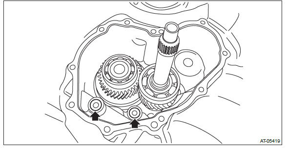
14) Remove the oil stopper plate and lubrication pipe.
15) Flip over the converter case.
16) Remove the oil pump chain cover and the oil pump chain. <Ref. to CVT-282, REMOVAL, Oil Pump Chain.>
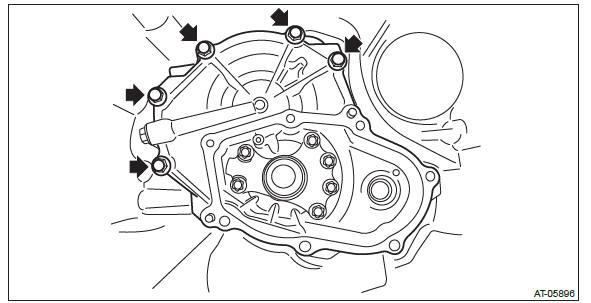
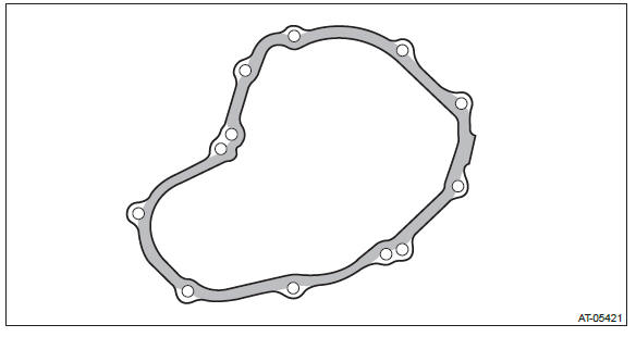
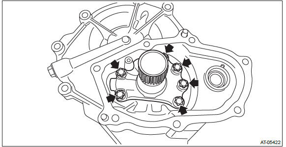
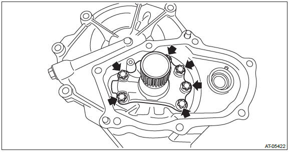
17) Remove the converter case cover.
18) Remove the O-ring.
19) Remove the seal ring from converter case cover.
B: INSTALLATION
1) Clean the mating surface of converter case cover and converter case.
2) Adjust the shims of front reduction drive gear and front reduction driven gear. <Ref. to CVT-302, ADJUSTMENT, Front Reduction Drive Gear.> <Ref. to CVT-311, ADJUSTMENT, Front Reduction Driven Gear.>
3) Install the O-ring.
NOTE:
- Use new O-rings.
- Apply CVTF to the O-ring.
4) Apply CVTF to the selected shims and install each to the catch surface of bearing.
5) Install the seal ring to converter case cover.
NOTE:
- Use a new seal ring.
- When installing the seal ring, do not expand the seal ring too much.
6) Apply liquid gasket seamlessly to the mating surface of converter case cover.
Liquid gasket: THREE BOND 1215 (Part No. 004403007) or equivalent
7) Install the converter case cover.
Tightening torque: 24 N*m (2.4 kgf-m, 17.7 ft-lb)

8) Install the oil pump chain cover and the oil pump chain. <Ref. to CVT-284, INSTALLATION, Oil Pump Chain.>
9) Flip over the converter case cover.
10) Install the oil stopper plate and lubrication pipe.
Tightening torque: 9 N*m (0.9 kgf-m, 6.6 ft-lb)
11) Install the drive pinion shaft assembly. <Ref. to CVT-244, INSTALLATION, Drive Pinion Shaft Assembly.>
12) Install the primary pulley, secondary pulley and variator chain. <Ref. to CVT-230, INSTALLATION, Primary Pulley and Secondary Pulley.>
13) Install the transmission case. <Ref. to CVT-213, INSTALLATION, Transmission Case.>
14) Install the forward clutch assembly. <Ref. to CVT-181, INSTALLATION, Forward Clutch Assembly.>
15) Install the intermediate case. <Ref. to CVT-166, INSTALLATION, Intermediate Case.>
16) Install the transfer reduction driven gear assembly. <Ref. to CVT-158, INSTALLATION, Transfer Reduction Driven Gear.>
17) Install the transfer clutch assembly. <Ref. to CVT-147, INSTALLATION, Transfer Clutch.>
18) Install the rear drive shaft. <Ref. to CVT-141, INSTALLATION, Rear Drive Shaft.>
19) Install the extension case. <Ref. to CVT-138, INSTALLATION, Extension Case.>
20) Install the transmission harness. <Ref. to CVT-123, INSTALLATION, Transmission Harness.>
21) Install the control valve body and oil pan. <Ref. to CVT-115, INSTALLATION, Control Valve Body.>
22) Install the air breather hose. <Ref. to CVT-132, INSTALLATION, Air Breather Hose.>
23) Install the transmission assembly to the vehicle. <Ref. to CVT-70, INSTALLATION, Automatic Transmission Assembly.>
C: DISASSEMBLY
1) Using ST, remove the center support COMPL.
ST 18270KA010 SOCKET (E16)
2) Remove the plug and O-ring.
D: ASSEMBLY
1) Install the plugs.
NOTE:
- Use new O-rings.
- Apply CVTF to the O-ring.
Tightening torque: 25 N*m (2.5 kgf-m, 18.4 ft-lb)

2) Using ST, install the center support COMPL.
ST 18270KA010 SOCKET (E16)
Tightening torque: 21.5 N*m (2.2 kgf-m, 15.9 ft-lb)
E: INSPECTION
- Check for leakage of CVTF from the connection between converter case and converter case cover.
Check there is no damage or cracks on the converter case cover.
F: ADJUSTMENT
When replacing the converter case cover, select the following shims.
- Select the shim for front reduction drive gear. <Ref. to CVT-302, ADJUSTMENT, Front Reduction Drive Gear.>
- Select the shim for front reduction driven gear. <Ref. to CVT-311, ADJUSTMENT, Front Reduction Driven Gear.>
READ NEXT:
 Front Reduction Drive Gear
A: REMOVAL
1) Remove the transmission assembly from the vehicle. <Ref. to CVT-55,
REMOVAL, Automatic Transmission
Assembly.>
2) Remove the air breather hose. <Ref. to CVT-132, REMOVAL, Air
Front Reduction Driven Gear
A: REMOVAL
NOTE:
For removal of front reduction driven gear, refer to the "Front Reduction Drive
Gear". <Ref. to CVT-297, REMOVAL,
Front Reduction Drive Gear.>
B: INSTALLATION
NOTE:
For install
Converter Case
A: REMOVAL
1) Remove the transmission assembly from the vehicle. <Ref. to CVT-55,
REMOVAL, Automatic Transmission
Assembly.>
2) Remove the air breather hose. <Ref. to CVT-132, REMOVAL, Air
SEE MORE:
Tire inspection
Check on a daily basis that the tires are free from serious damage, nails, and
stones. At the same time, check the tires for abnormal wear.
Contact your SUBARU dealer immediately if you find any problem.
NOTE
● When the wheels and tires strike curbs or are subjected to harsh treatment
a
Headlight Bulb
A: REMOVAL
1. HIGH BEAM
CAUTION:
Because the halogen bulb operates at a high temperature, dirt and oil
on the bulb surface reduces
the bulb's service life. Hold the flange portion when replacing the bulb.
Never touch the glass portion.
Do not leave the headlight without a bulb for a long tim
