Subaru Outback (BR): Cowl Panel
A: REMOVAL
1) Open the front hood.
2) Remove the front wiper arm assembly.
CAUTION: Follow the steps below when standing up the wiper arm. Not following the steps may cause contacting of wiper arms and damages of wiper arms.
1. Stand up the driver's side wiper arm.
2. Stand up the passenger's side wiper arm.
Fold the wiper arms in the reverse order.
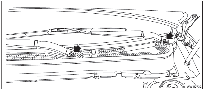
- Remove the cap.
- Remove the nuts, and remove the front wiper arm assembly.
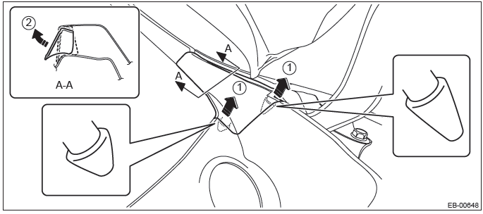
3) Remove the cowl panel side.
- Detach the pins of the cowl panel side.
- Remove the cowl panel side from inside the fender panel by pulling it.
CAUTION: Applying excessive pulling force may damage the cowl panel side. If it is difficult to remove, use a plastic remover or equivalent tool.
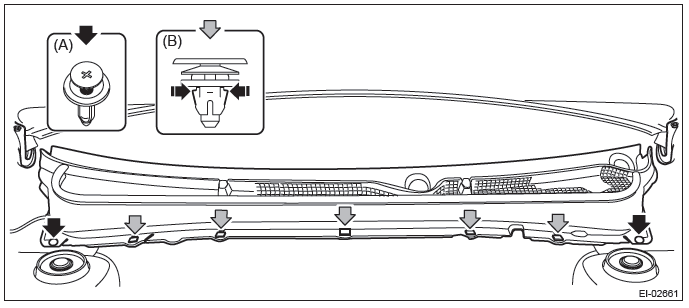
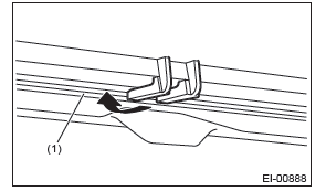
4) Remove the cowl panel.
- Release the clip (A).
- Push the claw of the clip (B) from both sides to remove it.
CAUTION: When removing the clip (B), push the claw of the clip from both sides.
The clip may be damaged if forcibly pulled.
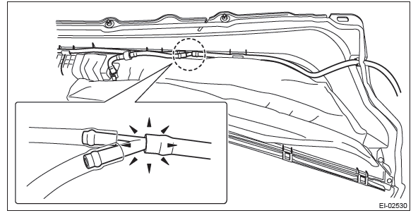
- Disconnect the washer hose.
B: INSTALLATION
Install each part in the reverse order of removal.
NOTE:
- Attach the claws of cowl panel to the bottom end of windshield.
- Cross section of windshield
- If the washer nozzles have been removed from the cowl panel, adjust the washer spray positions. <Ref. to WW-34, ADJUSTMENT, Front Washer Nozzle.>
Tightening torque:
Front wiper arm: <Ref. to WW-3, FRONT WIPER, COMPONENT, General Description.>
Front Under Cover
A: REMOVAL
1) Lift up the vehicle.
2) Remove the bolts and clips, and remove the front under cover.
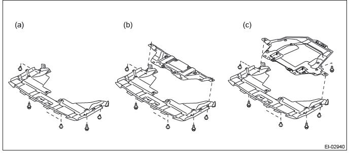
- Small type
- Medium type
- Large type
B: INSTALLATION
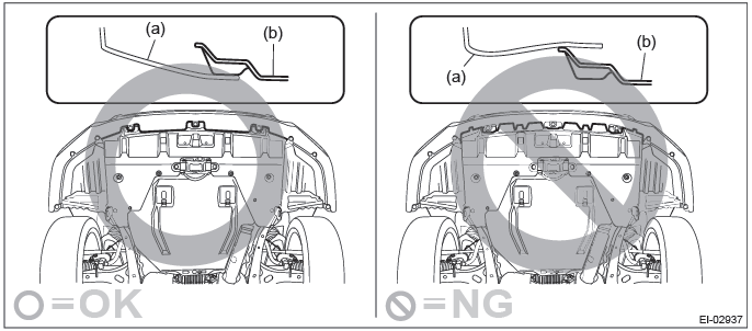
CAUTION: Install the under cover so that the under cover front end (b) comes inside of the front bumper face (a).
Install each part in the reverse order of removal.
Tightening torque: 17.5 N*m (1.78 kgf-m, 12.9 ft-lb)
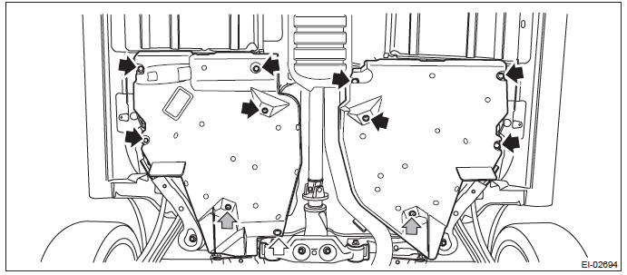
Floor Under Protector
A: REMOVAL
1) Lift up the vehicle.
NOTE: A plate type lift cannot be used.
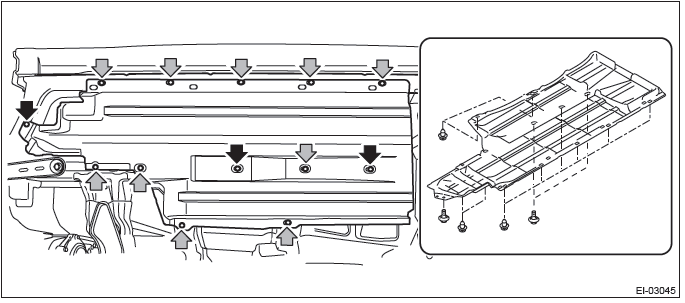
2) Remove the bolts and clips, and remove the front under protector.
B: INSTALLATION
Install each part in the reverse order of removal.
Tightening torque: Refer to "COMPONENT" of "General Description". <Ref. to EI-2, FLOOR UNDER PROTECTOR, COMPONENT, General Description.>
Fuel Tank Protector
A: REMOVAL
1) Lift up the vehicle.
2) Remove the fuel tank protector.
- Remove the bolt and nuts and remove the fuel tank protector.
- Remove the clip.
B: INSTALLATION
CAUTION: Do not reuse the nut (self locking nut). Always replace with a new part.
Install each part in the reverse order of removal.
Tightening torque: Refer to "COMPONENT" of "General Description". <Ref. to EI-3, FUEL TANK PROTECTOR, COMPONENT, General Description.>
Mud Guard
A: REMOVAL
1) Lift up the vehicle.
2) Remove the wheels.
3) Remove the clips, then remove the mud guard.
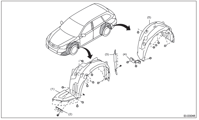
- Front mud guard
- Front air flap plate
- Fender cover lower
- Rear air flap plate
- Rear mud guard
B: INSTALLATION
Install each part in the reverse order of removal.
Tightening torque:
Wheel nut: 120 N*m (12.24 kgf-m, 88.5 ft-lb)
READ NEXT:
 Front Bumper
A: REMOVAL
1) Disconnect the ground cable from battery.
2) Remove the front bumper face assembly.
Remove the clips, turn over the front mud guard, and disconnect the fog
light connector. (Model w
Rear Bumper
A: REMOVAL
1) Remove the rear combination light assembly.
Sedan model
1. Remove the trunk room trim. <Ref. to EI-127, REMOVAL, Trunk Room Trim.>
2. Disconnect the connector.
3. Release the
Roof Molding
A: REMOVAL
CAUTION:
Be careful not to damage the body.
1) Remove the roof rail assembly. (OUTBACK model) <Ref. to EI-59, REMOVAL,
Roof Rail.>
2) Turn over the front end of roof molding.
3) Us
SEE MORE:
SRS side airbag and SRS curtain airbag
The SRS side airbag is stored in the door side of each front seat seatback, which
bears an “SRS AIRBAG” label.
In a moderate to severe side impact collision, the SRS side airbag on the impacted
side of the vehicle deploys between the occupant and the door panel and supplements
the seatbel
Components
1) Front sub sensor (right-hand side)
2) Front sub sensor (left-hand side)
3) SRS airbag system warning light
4) Frontal airbag module (driver’s side)
5) Front passenger’s frontal airbag ON and OFF indicator
6) Frontal airbag module (front passenger’s side)
7) Airbag control module (
