Subaru Outback (BR): Drive Pinion Shaft Assembly in Automatic Transmission
A: REMOVAL
1) Remove the transmission assembly from the vehicle.
<Ref. to 5AT-37, REMOVAL, Automatic Transmission Assembly.>
2) Pull out the torque converter assembly. <Ref. to 5AT-63, REMOVAL, Torque Converter Assembly.>
3) Remove the transmission harness connector from stay.
4) Remove the ATF cooler inlet pipe and outlet pipe. <Ref. to 5AT-58, REMOVAL, ATF Cooler Pipe and Hose.>
5) Separate the converter case and transmission case. <Ref. to 5AT-78, REMOVAL, Converter Case.>
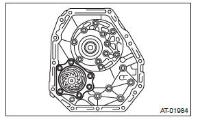
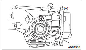
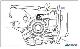
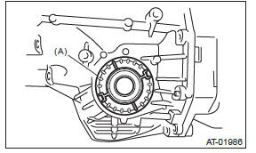
6) Remove the drive pinion shaft mounting bolts, and then remove the drive pinion shaft assembly from oil pump cover.
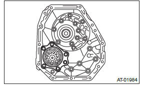
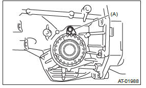
7) Remove the oil pump cover from AT main case.
<Ref. to 5AT-80, Oil Pump Cover.>
B: INSTALLATION
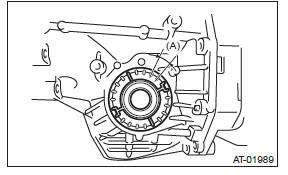
1) Assemble the drive pinion assembly to oil pump cover.
NOTE: Be careful not to bend the shim.
Tightening torque: 70 N*m (7.1 kgf-m, 51.6 ft-lb)
2) Adjust the tooth contact between drive pinion shaft assembly and the front differential side gear.
<Ref. to 5AT-86, ADJUSTMENT, Drive Pinion Shaft Assembly.>
3) Join the converter case with the transmission case. <Ref. to 5AT-78, INSTALLATION, Converter Case.>
4) Install the transmission harness connector to the stay.
5) Install the ATF cooler pipe. <Ref. to 5AT-59, INSTALLATION, ATF Cooler Pipe and Hose.>
6) Install the torque converter assembly. <Ref. to 5AT-63, INSTALLATION, Torque Converter Assembly.>
7) Install the transmission assembly to the vehicle.
<Ref. to 5AT-42, INSTALLATION, Automatic Transmission Assembly.>
C: DISASSEMBLY
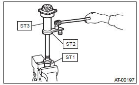
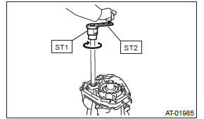
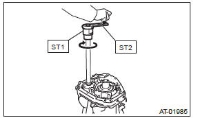
1) Flatten the lock nut tab, and then remove the lock nut while holding the rear spline part of the shaft using ST1 and ST2. Pull out the drive pinion collar.
ST1 18667AA010 HOLDER
ST2 499787700 WRENCH
ST3 499787500 ADAPTER
2) Remove the O-ring.
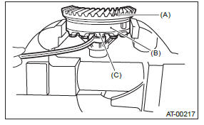
3) Separate the roller bearing and outer race from shaft using a press.
- Outer race
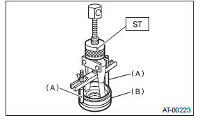
4) Separate the front roller bearing from the shaft using a press and the ST.
ST 498517000 REPLACER
- Front roller bearing
D: ASSEMBLY
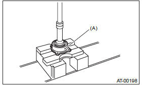
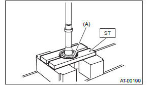
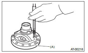
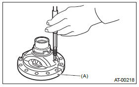
1) Measure the dimension "A" of drive pinion shaft.
ST 398643600 GAUGE
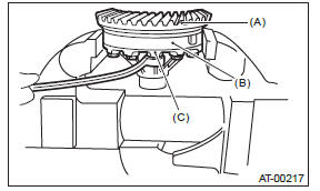
2) Using a press, press-fit the new roller bearing into the specified position.
NOTE: If excessive force is applied to roller bearing, the roller bearing will not turn easily.
- Drive pinion shaft
- Roller bearing
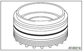
3) After fitting a new O-ring to the shaft, attach the drive pinion collar to the shaft.
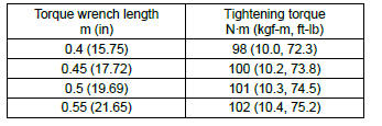
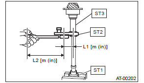
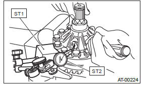
4) Tighten the new lock nuts using ST1, ST2 and ST3.
Calculate the tightening torque using following formula.
T2 = L2/(L1 + L2) × T1
T1: 116 N*m (11.8 kgf-m, 85.6 ft-lb)
[Required torque setting]
T2: Tightening torque
L1: ST2 length 0.072 m (2.83 in)
L2: Torque wrench length
Example:
ST1 18667AA010 HOLDER
ST2 499787700 WRENCH
ST3 499787500 ADAPTER
NOTE: Attach ST2 to torque wrench as straight as possible.
5) Measure the starting torque of the bearing. Make sure the starting torque is within the specified range. If the torque is not within specified range, replace the roller bearing.
Starting torque: 7.6 - 38.1 N (0.775 - 3.88 kgf, 1.7 - 8.6 lbf)
6) Crimp the locknut in 2 locations.
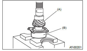
7) Measure the dimension "B" of the drive pinion shaft.
ST 398643600 GAUGE
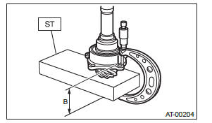
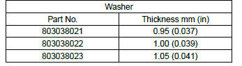
8) Calculate the thickness "t" mm (in) of the drive pinion shim.
t = 6.5+-0.0625 (0.256+-0.0025) - (B - A)
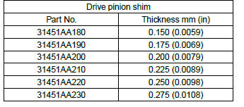
9) Select three or less shims from following table.
E: INSPECTION
- Make sure that all component parts are free of scratches, holes and other faults.
- Adjust the tooth alignment. <Ref. to 5AT-86, ADJUSTMENT, Drive Pinion Shaft Assembly.>
F: ADJUSTMENT
1) Assemble the drive pinion shaft assembly to oil pump cover.
2) Remove the liquid gasket from the mating surface completely.
3) Install the converter case to oil pump cover, and secure them with tightening four bolts evenly.
NOTE: Use an old gasket or aluminum washer to prevent damaging the mating surface of the housing.
Tightening torque: 41 N*m (4.2 kgf-m, 30.2 ft-lb)
4) Rotate the drive pinion a few times using ST1 and ST2.
ST1 18667AA010 HOLDER
ST2 499787700 WRENCH
5) Adjust the drive pinion and hypoid driven gear backlash. <Ref. to 5AT-92, ADJUSTMENT, Front Differential Assembly.>
6) Apply lead-free red dye evenly on the surface of three to four teeth of the hypoid driven gear. Rotate the drive pinion in the leftward and rightward for several times. Remove the oil pump cover, and check the tooth contact pattern.
If the teeth contact is inappropriate, adjust the backlash or thickness of the shim. <Ref. to 5AT-92, ADJUSTMENT, Front Differential Assembly.>
- Correct tooth contact
Check item: Tooth contact surface is slightly shifted toward the toe side under a no-load condition.
(When driving, it moves towards the heel side.
- Toe side
- Heel side
- Face contact
Check item: Backlash is too large.
Contact pattern
Adjustment: Increase the thickness of the shim according to the procedures for moving the drive pinion closer to the driven gear.
- Flank contact
Check item: Backlash is too small.
Contact pattern
Adjustment: Reduce the thickness of the shim according to the procedure for moving the drive pinion away from the driven gear.
- Toe contact (inside contact)
Check item: Teeth contact area is too small.
Contact pattern
Adjustment: Reduce the thickness of the shim according to the procedure for moving the drive pinion away from the driven gear.
- Heel contact (outside end contact)
Check item: Teeth contact area is too small.
Contact pattern
Adjustment: Increase the thickness of the shim according to the procedures for moving the drive pinion closer to the driven gear.
7) If tooth contact is correct, mark the retainer position and loosen it. After fitting a new O-ring and oil seal, screw in the retainer to the marked position.
Tighten the lock plate with specified torque.
Tightening torque: 25 N*m (2.5 kgf-m, 18.4 ft-lb)
- Lock plate
Front Differential Assembly
A: REMOVAL
1) Remove the transmission assembly from the vehicle. <Ref. to 5AT-37, REMOVAL, Automatic Transmission Assembly.>
2) Pull out the torque converter assembly. <Ref. to 5AT-63, REMOVAL, Torque Converter Assembly.>
3) Remove the transmission harness connector from stay.
4) Remove the ATF cooler inlet pipe and outlet pipe. <Ref. to 5AT-58, REMOVAL, ATF Cooler Pipe and Hose.>
5) Separate the converter case from the transmission case. <Ref. to 5AT-78, REMOVAL, Converter Case.>
6) Remove the differential side retainers using ST.
NOTE: Hold the differential case assembly by hand to avoid damaging the differential side retainer mounting hole of the converter case.
ST 18630AA010 WRENCH COMPL RETAINER
7) Remove the front differential assembly while being careful not to damage the attachment part of the retainer.
B: INSTALLATION
1) When installing the front differential assembly to the case, be careful not to damage the inside of case (particularly, the differential side retainer mating surface).
- Front differential ASSY
2) Install the O-ring to left and right side retainers.
3) Using the ST, install the side retainer. <Ref. to 5AT-92, ADJUSTMENT, Front Differential Assembly.>
ST 18630AA010 WRENCH COMPL RETAINER
4) Adjust the backlash of the front differential. <Ref. to 5AT-92, ADJUSTMENT, Front Differential Assembly.>
5) Install the lock plate.
Tightening torque: 25 N*m (2.5 kgf-m, 18.4 ft-lb)
- Lock plate
6) Install the converter case to the transmission case. <Ref. to 5AT-78, INSTALLATION, Converter Case.>
7) Install the transmission harness connector to the stay.
8) Install the ATF cooler pipe. <Ref. to 5AT-59, INSTALLATION, ATF Cooler Pipe and Hose.>
9) Install the torque converter assembly. <Ref. to 5AT-63, INSTALLATION, Torque Converter Assembly.>
10) Install the transmission assembly to the vehicle.
<Ref. to 5AT-42, INSTALLATION, Automatic Transmission Assembly.>
C: DISASSEMBLY
1. DIFFERENTIAL CASE ASSEMBLY
1) Remove the taper roller bearing using the ST and the press.
ST 498077000 REMOVER
2) Secure the case in a vise, remove the hypoid driven gear tightening bolts, and then separate the hypoid driven gear into case (RH) and case (LH).
- Hypoid driven gear
- Differential case (RH)
- Differential case (LH)
3) Pull out the straight pin and shaft, and then remove the differential bevel gear, washer and differential bevel pinion.
- Differential case (RH)
2. SIDE RETAINER
NOTE: After adjusting the drive pinion backlash and tooth contact, remove and install the oil seal and O-ring.
1) Remove the O-ring.
2) Remove the oil seal.
3) Remove the bearing outer race.
- Remove the split pin, and then remove the claw.
ST 398527700 PULLER ASSY
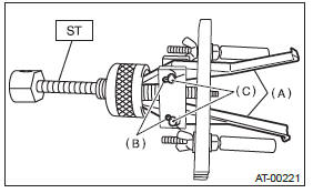
- Claw
- Split pin
- Pin
- Attach two claws to the outer race, and set the ST to side retainer.
ST 398527700 PULLER ASSY
- Shaft
- Claw
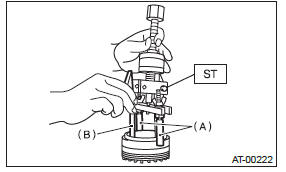
- Restore the removed claws to original position, and install the pin and split pin.
- Hold the shaft of ST to avoid removing from side retainer, and then remove the bearing outer race.
NOTE: Replace the bearing inner and outer races as a single unit.
ST 398527700 PULLER ASSY
- Shaft
- Side retainer
D: ASSEMBLY
1. DIFFERENTIAL CASE ASSEMBLY
1) Install the washer, differential bevel gear and differential bevel pinion in the differential case (RH).
Insert the pinion shaft.
2) Attach the straight pin in the reverse direction.
- Differential case (RH)
3) Install the washer and differential bevel gear to differential case (LH). Put the differential case (LH) on the differential case (RH), and assemble the two differential cases.
4) Install the hypoid driven gear and secure by tightening the bolt.
Tightening torque: 70 N*m (7.1 kgf-m, 51.6 ft-lb)
- Hypoid driven gear
- Differential case (RH)
- Differential case (LH)
5) Measurement of backlash (Selection of washer)
- Install the SUBARU genuine axle shaft to differential case.
Part No. 38415AA070 Axle shaft
- Measure the gear backlash using ST1 and ST2, and then insert the ST2 through the access window of differential case.
NOTE:
- Measure the backlash by applying a differential bevel pinion tooth between two differential bevel gear teeth.
- When measuring, fix the differential bevel pinion gear in place with a screwdriver covered with waste cloth, or a similar tool.
Standard: 0.13 - 0.18 mm (0.0051 - 0.0071 in)
ST1 498247001 MAGNET BASE
ST2 498247100 DIAL GAUGE
- If the backlash is not within specification, select a washer from the table below.
6) Using the ST, install the taper roller bearing.
ST 398487700 DRIFT
2. SIDE RETAINER
NOTE: Install the oil seal and O-ring of side retainer after the adjustment of backlash and tooth contact.
1) Install the bearing outer race to side retainer.
2) Using the ST, install the oil seal.
NOTE:
- Use a new oil seal.
- Apply gear oil to the oil seal lips, and install the oil seal while being careful not to deform the lip.
- Check the identification marks (L, R) during installation not to mix up the oil seal RH and LH.
ST 18675AA000 DIFFERENTIAL SIDE OIL SEAL INSTALLER
3) Install a new O-ring.
E: INSPECTION
- Check each component for scratches, damage or other faults.
- Measure the backlash, and then adjust it to be within specification. <Ref. to 5AT-92, ADJUSTMENT, Front Differential Assembly.>
F: ADJUSTMENT
1) Using the ST, screw-in the retainer until resistance is felt.
NOTE: Screw-in the retainer RH side slightly deeper than the retainer LH.
ST 18658AA020 WRENCH COMPL RETAINER
2) Remove the oil pump cover.
3) Remove the liquid gasket from the mating surface completely.
4) Install the oil pump cover to converter case, and secure them with tightening four bolts evenly.
NOTE: Use an old gasket or aluminum washer to prevent damaging the mating surface of the housing.
Tightening torque: 41 N*m (4.2 kgf-m, 30.2 ft-lb)
5) Rotate the drive pinion ten times or more using ST1 and ST2.
ST1 18667AA010 HOLDER
ST2 499787700 WRENCH
6) Tighten the LH retainer by rotating the shaft until resistance is felt. Then loosen the retainer RH.
Keep tightening the retainer LH, and loosening the retainer RH until the pinion shaft no longer be turned. This is the "zero" state.
- Retainer
7) After the "zero" state is established, loosen the retainer LH by 3 notches and secure it with the lock plate. Then loosen the retainer RH and retighten until it stops. Rotate the drive pinion 2 or 3 times.
Tighten the retainer RH further 1-3/4 notches. This sets the preload. Finally, secure the retainer with its lock plate.
- Lock plate
NOTE: Turning the retainer by one tooth changes the backlash approx. 0.05 mm (0.0020 in).
- 0.05 mm (0.0020 in)
8) Install the SUBARU genuine axle shaft to the left and right sides of the front differential.
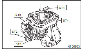
9) Turn the drive pinion a few times with ST1 and check to see if the backlash is within the specified value, using ST2, ST3, ST4 and ST5.
NOTE: Secure the ST1 and stator shaft with the tie-wrap.
Backlash: 0.13 - 0.18 mm (0.0051 - 0.0071 in)
ST1 499787700 WRENCH
ST2 498247001 MAGNET BASE
ST3 498247100 DIAL GAUGE
ST4 499787500 ADAPTER
ST5 498255400 PLATE
10) Adjust the teeth contact of the front differential and drive shaft. <Ref. to 5AT-86, ADJUSTMENT, Drive Pinion Shaft Assembly.>
READ NEXT:
 AT Main Case
A: REMOVAL
1) Remove the transmission assembly from the vehicle.
<Ref. to 5AT-37, REMOVAL, Automatic
Transmission Assembly.>
2) Pull out the torque converter assembly. <Ref. to
5AT-63, REMO
Automatic Transmission Control Device
A: REMOVAL
1) Remove the transmission assembly from the vehicle.
<Ref. to 5AT-37, REMOVAL, Automatic Transmission Assembly.>
2) Pull out the torque converter assembly. <Ref. to 5AT-63, REM
SEE MORE:
Front Speaker
A: REMOVAL
1. FRONT SIDE SPEAKER
1) Disconnect the ground cable from battery.
2) Remove the front side speaker.
Release the clips and claws, then detach the speaker cover.
CAUTION:
Use a plastic clip remover for removal.
Remove the screws.
Preparation tool: Stubby screwdriver
Disconnect the
Unfastening the rear center seatbelt
Push the release button of the center seatbelt buckle (on the left-hand side)
to unfasten the seatbelt.
1. Insert a key or other hard pointed object into the slot in the connector (buckle)
on the right-hand side and push it in, and the connector (tongue) plate will disconnect
from the b
