Subaru Outback (BR): Drive Pinion Shaft Assembly in Manual Transmission
A: REMOVAL
1) Remove the manual transmission assembly from the vehicle. <Ref. to 6MT-25, REMOVAL, Manual Transmission Assembly.>
2) Remove the transfer case together with the extension case assembly. <Ref. to 6MT-40, REMOVAL, Transfer Case and Extension Case Assembly.>
3) Remove the transmission case. <Ref. to 6MT- 57, REMOVAL, Transmission Case.>
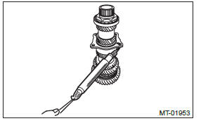
4) Remove the drive pinion shaft assembly.
NOTE: Use a hammer handle, etc. to remove if too tight.
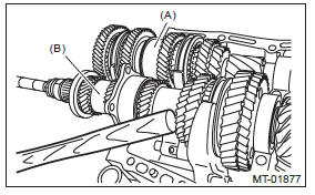
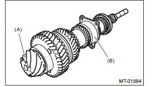
- Main shaft ASSY for single-range
- Drive pinion shaft ASSY
B: INSTALLATION
1) Remove the front differential assembly.
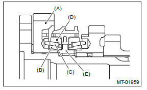
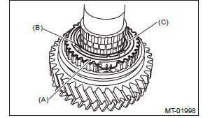
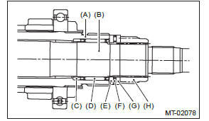
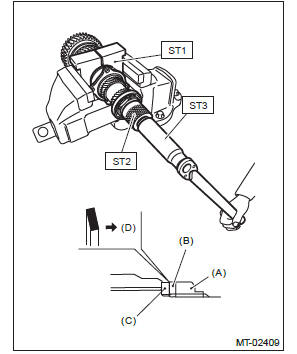
2) Hypoid gear set match mark/No.: The number (A) on top of the drive pinion, and the number on the hypoid driven gear are set numbers for the two gears. Use a pair having the same numbers.
The figure (B) below shows a number for shim adjustment.
If no number is shown, the value is zero.
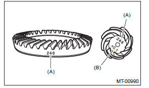
- Set number
- Number for shim adjustment
3) Place the drive pinion shaft assembly on transmission main case RH without shim and tighten the bearing mounting bolts.
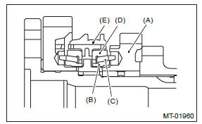
4) Check and adjust the ST.
NOTE:
- Loosen the two bolts and adjust so that the scale indicates 0.5 correctly when the plate end and the scale end are on the same level.
- Tighten the two bolts.
ST 499917500 DRIVE PINION GAUGE ASSY
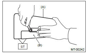
- Plate
- Scale
5) Position the ST by inserting the knock pin of ST into the knock hole of transmission case.
ST 499917500 DRIVE PINION GAUGE ASSY
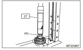
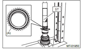
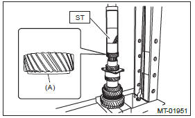
6) Slide the drive pinion gauge scale with finger tip and read the value at the point where it matches with the end face of drive pinion.
ST 499917500 DRIVE PINION GAUGE ASSY
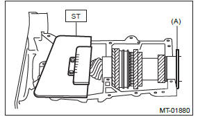
- Adjust the clearance to zero without shim.
7) The thickness of shim shall be determined by adding the value indicated on drive pinion to the value indicated on the ST. (Add if the number on drive pinion is prefixed by +, and subtract if the number is prefixed by -.) ST 499917500 DRIVE PINION GAUGE ASSY
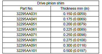
8) Select one to three shims in the following table for the value determined as described above, and take the shim(s) which thickness is closest to the said value.
NOTE: Install the shim with it's cut in facing the shifter fork & rod side.
9) Install the front differential assembly. <Ref. to 6MT-77, INSTALLATION, Front Differential Assembly.>
10) Fit the transmission case knock pin to the knock pin hole of the roller bearing and install the drive pinion shaft assembly.
11) Install the main shaft assembly for single-range.
<Ref. to 6MT-60, INSTALLATION, Main Shaft Assembly for Single-Range.>
12) Check each shifter fork. <Ref. to 6MT-92, INSPECTION, Shifter Fork and Rod.>
13) Install the transmission case. <Ref. to 6MT-58, INSTALLATION, Transmission Case.>
14) Install the transfer case together with the extension case assembly. <Ref. to 6MT-40, INSTALLATION, Transfer Case and Extension Case Assembly.>
15) Install the manual transmission assembly to the vehicle. <Ref. to 6MT-29, INSTALLATION, Manual Transmission Assembly.>
C: DISASSEMBLY
NOTE:
- Attach a cloth to the end of driven shaft (on the frictional side of the thrust needle bearing) to prevent damage during disassembly or reassembly.
- If necessary, use a new gear and hub assembly as a set, when replacing the gear or hub. Because these must engage at the specified point, avoid disassembly as much as possible. If it must be disassembled, mark the engaging point on the spline beforehand.
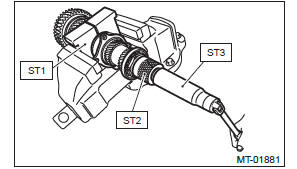
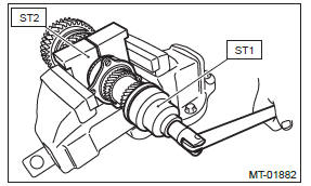
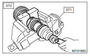
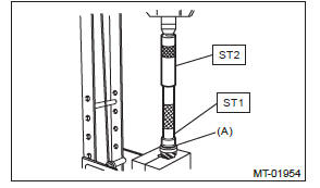
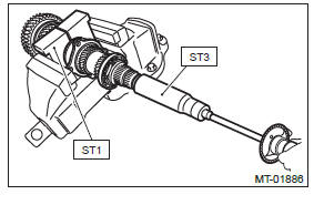
1) Flatten the tab of the lock nut. Remove the lock nut with ST1, ST2 and ST3.
ST1 18680AA020 HOLDER
ST2 18667AA020 HOLDER
ST3 18662AA010 SOCKET WRENCH (27)
2) Draw out the drive pinion from driven shaft.
Remove the differential bevel gear sleeve, adjusting washer No. 1, adjusting washer No. 2, thrust bearing, needle bearing and drive pinion collar.
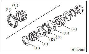
- Differential bevel gear sleeve
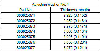
- Adjusting washer No. 1 (25 × 36 × t)
- Thrust bearing (25 × 36 × 2)
- Adjusting washer No. 2 (25 × 36 × t)
- Needle bearing (25 × 30 × 20)
- Drive pinion collar
- Needle bearing (30 × 37 × 23)
- Thrust bearing (33 × 50 × 3)
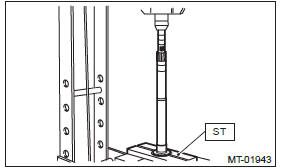
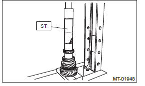
3) Remove the roller bearing and washer using ST and a press.
NOTE: Do not reuse the roller bearing.
ST 498077000 REMOVER
4) Flatten the tab of the lock nut. Remove the lock nut using ST1 and ST2.
ST1 499987300 SOCKET WRENCH (50)
ST2 18680AA020 HOLDER
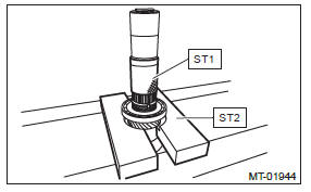
5) Remove the ball bearing, 6th driven gear and drive pinion spacer using the ST1, ST2 and a press.
ST1 899754112 PRESS
ST2 899714110 REMOVER
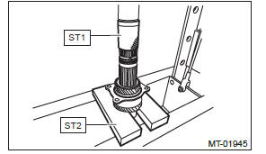
6) Remove the taper roller bearing and 3rd-4th driven gear using ST1, ST2 and a press.
ST1 899754112 PRESS
ST2 899714110 REMOVER
7) Remove the key.
8) Remove the 2nd driven gear, inner baulk ring, synchro cone, outer baulk ring and 1st-2nd coupling sleeve.
9) Remove the 1st driven gear, inner baulk ring, synchro cone, outer baulk ring, 2nd gear bushing and 1st-2nd synchronizer hub using ST and a press.
ST 18762AA000 COMPRESSOR SPECIAL TOOL
D: ASSEMBLY
1) Install the sleeve and the gear and hub assembly by matching the alignment marks.
NOTE:
- Position the open ends of the spring 120º apart.
- Use the new gear & hub assembly, if replacing the gear or hub.
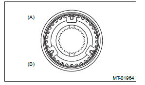
- 1st-2nd sleeve & hub ASSY
- 1st gear side
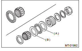
2) Install the 1st driven gear, inner baulk ring, synchro cone and outer baulk ring and 1st-2nd synchronizer hub onto driven shaft.
NOTE:
- Install the gear & hub assembly in the proper position while paying attention to the installing direction.
- Align the baulk ring and gear & hub assembly with the key groove.
- 1st driven gear
- Inner baulk ring
- Synchro cone
- Outer baulk ring
- 1st-2nd synchronizer hub
3) Install the 2nd driven gear bushing onto driven shaft using ST and a press.
CAUTION: Do not apply a load in excess of 10 kN (1 ton, 1.1 US ton, 1.0 Imp ton).
NOTE:
- Attach a cloth to the end of the driven shaft to prevent damage.
- When press fitting, align the oil holes of the shaft and bushing
ST 18654AA000 INSTALLER
- 2nd driven gear bushing
4) Attach the 1st-2nd coupling sleeve and 1st-2nd shifting insert key to the driven shaft.
NOTE:
- Install the 1st-2nd coupling sleeve with the long flange side facing the 1st driven gear.
- Install the 1st-2nd shifting insert keys at 120º interval positions.
- 1st-2nd coupling sleeve
- 1st-2nd shifting insert key (three positions)
5) Install the outer baulk ring, synchro cone, inner baulk ring and 2nd driven gear to driven shaft.
NOTE: Align the groove in baulk ring with the insert.
- Outer baulk ring
- Synchro cone
- Inner baulk ring
- 2nd driven gear
- Inner baulk ring
- Synchro cone
- Outer baulk ring
- 1st-2nd coupling sleeve
6) After installing key on driven shaft, install the 3rd-4th driven gear using a ST and a press.
CAUTION: Do not apply a load in excess of 10 kN (1 ton, 1.1 US ton, 1.0 Imp ton).
ST 499277200 INSTALLER
7) Install a set of roller bearings onto the driven shaft using ST and a press.
CAUTION: Do not apply a load in excess of 10 kN (1 ton, 1.1 US ton, 1.0 Imp ton).
ST 499277200 INSTALLER
8) Install the 5th driven gear onto driven shaft using ST and a press.
CAUTION: Do not apply a load in excess of 10 kN (1 ton, 1.1 US ton, 1.0 Imp ton).
NOTE: Install the 5th driven gear with the groove side facing the 6th driven gear.
ST 499277200 INSTALLER
- Install with the groove side facing the 6th driven gear.
9) Install the drive pinion spacer to driven shaft, then install the 6th driven gear to driven shaft using the ST and a press.
CAUTION: Do not apply a load in excess of 10 kN (1 ton, 1.1 US ton, 1.0 Imp ton).
NOTE: Install the 6th driven gear with the stepped side facing the 5th driven gear.
ST 499277200 INSTALLER
- Install with the stepped side facing the 5th driven gear.
10) Install the ball bearing onto driven shaft using ST and a press.
CAUTION: Do not apply a load in excess of 10 kN (1 ton, 1.1 US ton, 1.0 Imp ton).
ST 499277200 INSTALLER
11) Tighten the lock nuts to the specified torque using ST1 and ST2.
NOTE: Use a new lock nut.
Tightening torque: 440 N*m (44.9 kgf-m, 324.5 ft-lb)
ST1 499987300 SOCKET WRENCH (50)
ST2 18680AA020 HOLDER
12) Using a spring scale, check that starting torque of the roller bearing is 0.1 to 1.5 N (0.01 to 0.15 kgf, 0.02 to 0.34 lbf).
13) Crimp the locknut in 2 locations.
14) Install the roller bearing onto drive pinion.
NOTE: When installing the roller bearing, direct the knock pin hole of outer race toward rear.
- Roller bearing
- Knock pin hole
15) Install the washer using ST1, ST2 and a press.
CAUTION: Do not apply a load in excess of 10 kN (1 ton, 1.1 US ton, 1.0 Imp ton).
ST1 499277100 BUSHING 1-2 INSTALLER
ST2 499277200 INSTALLER
- Washer
16) Install the thrust bearing and needle bearing.
Install the driven shaft assembly.
17) Install the drive pinion collar, needle bearing, adjusting washer No. 2, thrust bearing, adjusting washer No. 1 and differential bevel gear sleeve in this order.
- Driven shaft
- Drive pinion shaft
- Drive pinion collar
- Needle bearing (25 × 30 × 20)
- Adjusting washer No. 2 (25 × 36 × t)
- Thrust bearing (25 × 36 × 2)
- Adjusting washer No. 1 (25 × 36 × t)
- Differential bevel gear sleeve
18) Adjust the thrust bearing preload. <Ref. to 6MT-74, THRUST BEARING PRELOAD, ADJUSTMENT, Drive Pinion Shaft Assembly.>
E: INSPECTION
Disassembled parts should be washed with cleaning solvent first, then inspected carefully.
1) Bearing
Replace the bearings in the following cases.
- When the bearing balls, outer races and inner races are broken or rusty.
- When the bearing is worn.
- When the bearings fail to turn smoothly or emit noise in rotation after gear oil lubrication.
- The ball bearing on the rear side of the drive pinion shaft should be checked for smooth rotation before the drive pinion assembly is disassembled. In this case, because a preload is working on the bearing, its rotation feels like it is slightly dragging unlike other bearings.
- Drive pinion shaft
- Ball bearing
- When bearing has other defects.
2) Bushing (each gear)
Replace the bushing in following cases.
- When the sliding surface is damaged or abnormally worn.
- When the inner wall is abnormally worn.
3) Gear
Replace gears in the following cases.
- Replace the gear with new part if its tooth surfaces are broken, damaged or excessively worn.
- Correct or replace if the cone that contacts the baulk ring is rough or damaged.
- Correct or replace if the inner surface or end face is damaged.
4) Baulk ring, synchro cone
Replace the baulk ring and synchro cone in the following cases.
- When the inner surface or end face is damaged.
- When the baulk ring inner surface is abnormally or partially worn down.
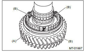
- If the gap between the end faces of the baulk ring and the gear splined part is excessively small, check the clearance (A) while pressing the ring against the cone.
Clearance (A): 0.5 mm (0.020 in) or more
- When the contact surface of the synchronizer ring insert section is scratched or abnormally worn.
- Apply gear oil to the corn of the gear and while press-fitting the synchronizer ring, check there is no rotation in the circumferential direction.
5) Coupling sleeve and synchronizer hub
- Check the slipping condition of the coupling sleeve.
- Check the splines on the coupling sleeve and synchronizer hub for wear.
6) Shifting insert key
Replace the shifting insert key if deformed, excessively worn or defective in any way.
F: ADJUSTMENT
1. THRUST BEARING PRELOAD
1) Select a suitable adjusting washer No. 1 so that dimension (H) will be zero in a visual check. Position the washer (20 × 31 × 4) and lock washer (20 × 31 × 2.3) and attach the lock nut.
2) Using the ST1, ST2 and ST3, tighten the lock nut to the specified torque.
NOTE:
- Use new lock nuts and lock washers.
- Make sure the lock washer is installed in the proper direction.
Tightening torque: 126 N*m (12.8 kgf-m, 92.9 ft-lb)
ST1 18680AA020 HOLDER
ST2 18667AA020 HOLDER
ST3 18662AA010 SOCKET (27)
- Nut
- Lock washer
- Washer
- Nut side
3) After removing the ST2 used in step 2), measure the starting torque using torque driver.
Starting torque: 0.3 - 0.8 N*m (0.03 - 0.08 kgf-m, 0.2 - 0.6 ft-lb)
ST1 18680AA020 HOLDER
ST3 18662AA010 SOCKET (27)
4) If the starting torque is not within the specified limit, select new adjusting washer No. 1 and recheck starting torque.
- Adjusting washer No. 1
- Adjusting washer No. 2
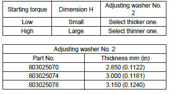
5) If the specified starting torque cannot be obtained by the selection of adjusting washer No. 1, select adjusting washer No. 2 from the list below.
Repeat steps 1) through 4) to adjust starting torque.
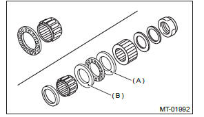
- Adjusting washer No. 1
- Adjusting washer No. 2
6) Recheck that the starting torque is within the specified range, then crimp the lock nut at four positions.
READ NEXT:
 Front Differential Assembly in Manual Transmission
A: REMOVAL
1) Remove the manual transmission assembly from the vehicle. <Ref. to 6MT-25, REMOVAL, Manual Transmission Assembly.>
2) Remove the transfer case together with the extension case as
Reverse Idler Gear
REMOVAL
1) Remove the manual transmission assembly
from the vehicle. <Ref. to 6MT-25, REMOVAL,
Manual Transmission Assembly.>
2) Remove the back-up light switch neutral position
switch. <Ref
Shifter Fork and Rod
A: REMOVAL
1) Remove the manual transmission assembly
from the vehicle. <Ref. to 6MT-25, REMOVAL,
Manual Transmission Assembly.>
2) Remove the back-up light switch and the neutral
position swit
SEE MORE:
DTC P0128, P0131, P0132, P0133, P0134, P0137, P0138, P013A, P013B, P013E,
P013F, P0140, P0141, P014C, P014D, P015A, P015B, P0171, P0172, P0181, P0182,
P0183, P0196, P0197, P0198, P0201
AA:DTC P0128 COOLANT THERMOSTAT (ENGINE COOLANT TEMPERATURE
BELOW THERMOSTAT REGULATING TEMPERATURE)
DTC DETECTING CONDITION:
Detected when two consecutive driving cycles with fault occur.
GENERAL DESCRIPTION <Ref. to GD(H4SO)-55, DTC P0128 COOLANT THERMOSTAT
(ENGINE
COOLANT TEMPERATURE BEL
Transfer Case and Extension
Case Assembly
A: REMOVAL
1) Remove the manual transmission assembly
from the vehicle. <Ref. to 6MT-25, REMOVAL,
Manual Transmission Assembly.>
2) Remove the back-up light switch and the neutral
position switch. <Ref. to 6MT-37, REMOVAL,
Switches and Harness.>
3) Remove the transfer case together wit
