Subaru Outback (BR): Front Stabilizer
A: REMOVAL
1) Lift up the vehicle, and then remove the left and right front wheels.
2) Remove the front under cover. <Ref. to EI-35, REMOVAL, Front Under Cover.>
3) Remove the center exhaust pipe. (turbo model) <Ref. to EX(H4DOTC)-12, REMOVAL, Center Exhaust Pipe.>
4) Remove the front stabilizer.
- Remove the left and right stabilizer links.
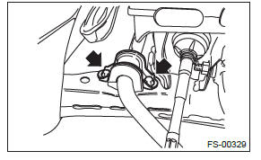
- Remove the left and right stabilizer brackets.
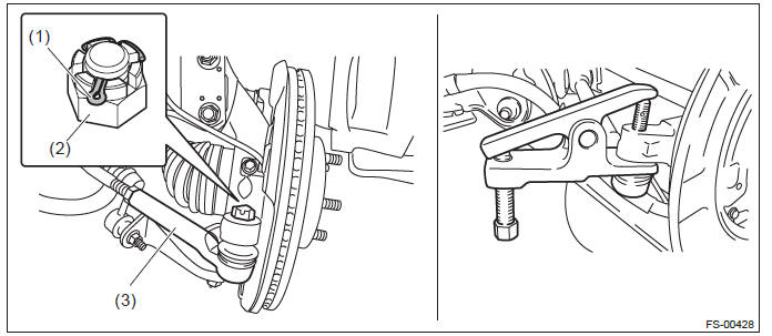
- Disconnect the left and right tie-rod ends.
- Pull out the cotter pin.
- Remove the castle nut.
- Extract the tie-rod end from the front axle housing.
PREPARATION TOOL: Tie-rod end puller
- Cotter pin
- Castle nut
- Tie-rod end
- Suspend the engine and replace the front cushion mount with ST. (turbo model) <Ref. to 5AT-37, REMOVAL, Automatic Transmission Assembly.>
PREPARATION TOOL: ST: SPECIAL TOOL - H4 (41099AJ000)
NOTE: For turbo model, it is required to secure space for operation to hang the engine and remove the stabilizer.
- Turn the front stabilizer by approximately 180º toward the front of the vehicle and pull out the front stabilizer from the right side of the vehicle.
- Turn toward the front of the vehicle.
- Front side of vehicle
B: INSTALLATION
1) Before installation, inspect the following items and replace any faulty part with a new one.
- Check the bushing for abnormal cracks, fatigue or damage.
- Check the stabilizer link for damage.
2) Install each part in the reverse order of removal.
CAUTION: The stabilizer bracket has a set orientation. Install it with the arrow mark facing the front side (1) of the vehicle.
Tightening torque:
Stabilizer bracket: 25 N*m (2.55 kgf-m, 18.4 ft-lb)
Stabilizer link: 60 N*m (6.12 kgf-m, 44.3 ft-lb)
READ NEXT:
 Front Ball Joint
A: REMOVAL
1) Lift up the vehicle, and then remove the front wheels.
2) Remove the left and right stabilizer brackets.
3) Remove the ball joint.
Extract the cotter pin (a) from the ball stud.
Rem
Front Arm
A: REMOVAL
1) Lift up the vehicle, and then remove the front wheels.
2) Remove the front arm.
Remove the nut and disconnect the front stabilizer link.
Remove the bolt, and then remove the ball joi
Front Strut
A: REMOVAL
1) Lift up the vehicle, and then remove the front wheels.
2) Remove the front strut.
Place an alignment mark on the camber adjusting bolt and strut.
Remove the brake hose bracket.
R
SEE MORE:
Rear wiper
To turn the rear wiper on, turn the knob on the end of the wiper control lever
upward to the “INT” or “ON” position. To turn the wiper off, return the knob on
the end of the lever to the “OFF” position. With the switch turned to the “INT”
position, the rear wiper will operate i
Air Conditioning System
A: WIRING DIAGRAM
Refer to "Air Conditioning System" in the wiring diagram. <Ref. to WI-53,
WIRING DIAGRAM, Air Conditioning
System.>
B: ELECTRICAL SPECIFICATION
Refer to "Auto A/C Control Module I/O Signal" of "HVAC SYSTEM (DIAGNOSTICS)"
section. <Ref. to AC(diag)-
6, ELECTRICAL SPECIFIC
