Subaru Outback (BR): General Description of Drive Shaft System
Subaru Outback (BR) 2010-2015 Service Manual / Chassis / Drive Shaft System / General Description of Drive Shaft System
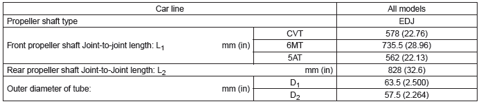
A: SPECIFICATION
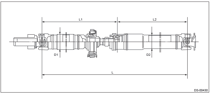
1. PROPELLER SHAFT
2. FRONT DRIVE SHAFT ASSEMBLY

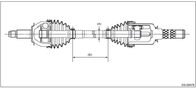
- Axle diameter
- Axle length
3. REAR DRIVE SHAFT ASSEMBLY

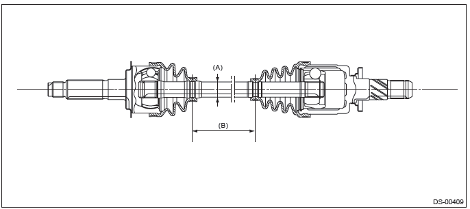
- Axle diameter
- Axle length
B: COMPONENT
1. PROPELLER SHAFT
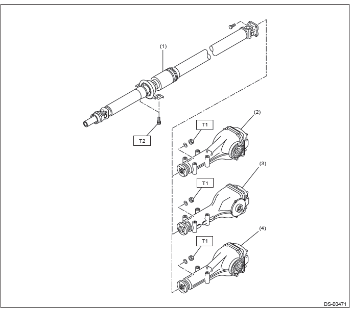
- Propeller shaft
- Rear differential (VA1-type)
- Rear differential (T-type)
- Rear differential (VA2-type)
Tightening torque: N*m (kgf-m, ft-lb)
T1: 31 (3.16, 22.9)
T2: 52 (5.3, 38.4)
2. FRONT AXLE
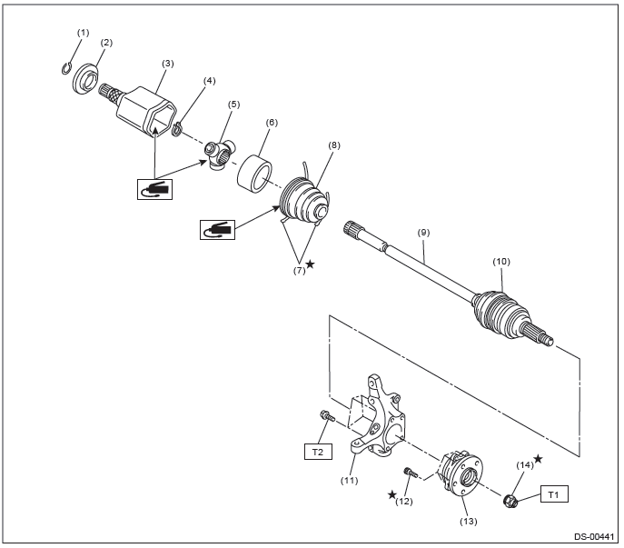
- Circlip
- Baffle plate
- Outer race (AAR)
- Snap ring
- Trunnion
- Grommet
- Boot band
- Boot (AAR)
- AC shaft ASSY
- Boot (AC)
- Front axle housing
- Hub bolt
- Front hub unit bearing
- Axle nut
Tightening torque: N*m (kgf-m, ft-lb)
T1: 220 (22.43, 162.3)
T2: 65 (6.63, 47.9)
3. REAR AXLE
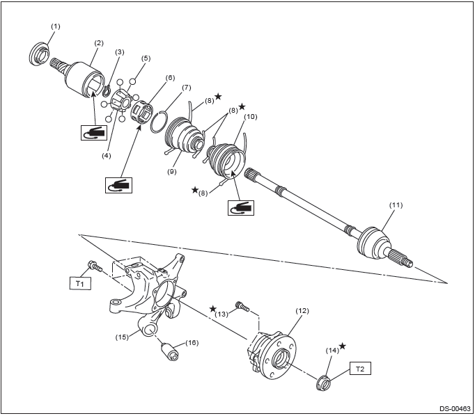
- Baffle plate
- Outer race (DOJ)
- Snap ring
- Inner race
- Ball
- Cage
- Snap ring
- Boot band
- Boot (DOJ)
- Boot (BJ)
- BJ shaft ASSY (sedan CVT model)
EBJ shaft ASSY (except for sedan CVT model) - Rear hub unit bearing
- Hub bolt
- Axle nut
- Rear axle housing
- Rear bushing
Tightening torque:N*m (kgf-m, ft-lb)
T1: 65 (6.63, 47.9)
T2: 240 (24.47, 177.0)
C: CAUTION
- Wear appropriate work clothing, including a helmet, protective goggles and protective shoes when performing any work.
- Remove contamination including dirt and corrosion before removal, installation or disassembly.
- Keep the disassembled parts in order and protect them from dust and dirt.
- Before removal, installation or disassembly, be sure to clarify the failure. Avoid unnecessary removal, installation, disassembly and replacement.
- Vehicle components are extremely hot after driving. Be wary of receiving burns from heated parts.
- Use SUBARU genuine grease etc. or equivalent. Do not mix grease etc. of different grades or manufacturers.
- Be sure to tighten fasteners including bolts and nuts to the specified torque.
- Place shop jacks or rigid racks at the specified points.
- Apply grease onto sliding or revolving surfaces before installation.
- Before installing snap rings, apply sufficient amount of grease to avoid damage and deformation.
- Before securing a part on a vise, place cushioning materials such as wood blocks, aluminum plates, or waste cloth between the part and the vise.
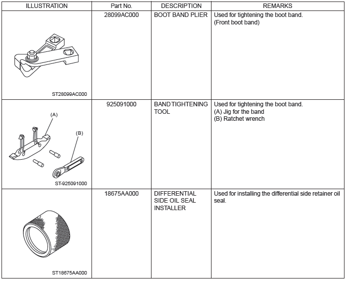
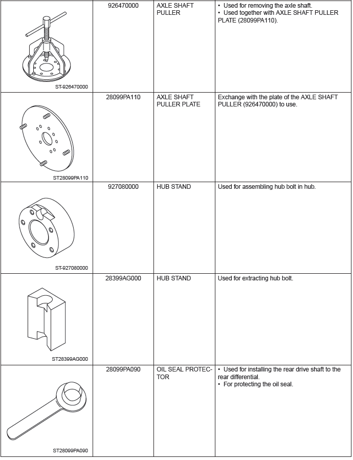
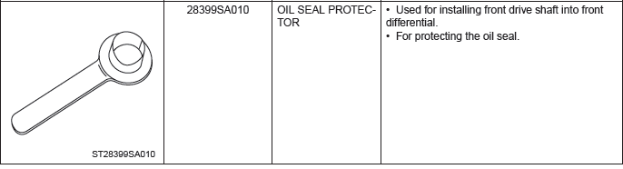
D: PREPARATION TOOL
1. SPECIAL TOOL
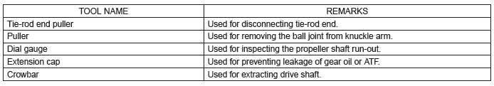
2. GENERAL TOOL
READ NEXT:
 Propeller Shaft
A: REMOVAL
CAUTION:
Do not disassemble the center EDJ of the propeller shaft.
Before removing propeller shaft, wrap the metal parts attached to the
rubber boot of center EDJ
with a cloth or rubb
Front Axle
A: REMOVAL
1) Lift up the vehicle, and then remove the front wheels.
2) Remove the axle nut.
CAUTION:
Do not loosen the axle nut while the front axle is loaded. Doing so may damage
the hub bearing.
Front Hub Unit Bearing
A: REMOVAL
1) Lift up the vehicle, and then remove the front wheels.
2) Remove the axle nut.
CAUTION:
Do not loosen the axle nut while the front axle is loaded. Doing so may damage
the hub bearing.
SEE MORE:
Rear Axle
A: REMOVAL
1) Lift up the vehicle, and then remove the rear wheels.
2) Remove the axle nut.
CAUTION:
Do not loosen the axle nut while the rear axle is loaded. Doing so may damage
the hub bearing.
Lift the crimped section of axle nut.
Remove the axle nut using a socket wrench while depressing th
Airflow control buttons
Each airflow control button activates the following air outlets.
: Instrument panel outlets
: Instrument panel outlets and foot
outlets
: Foot outlets, both side outlets of
the instrument panel and some through windshield defroster outlets (A small amount
of air flows to the windshield
© 2010-2026 Copyright www.suoutback.com
