Subaru Outback (BR): Propeller Shaft
A: REMOVAL
CAUTION:
- Do not disassemble the center EDJ of the propeller shaft.
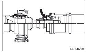
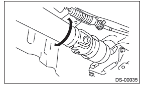
- Before removing propeller shaft, wrap the metal parts attached to the rubber boot of center EDJ with a cloth or rubber material, as shown in the figure. The rubber boot may be damaged due to interference with adjacent metal parts while bending the EDJ during removal.
1) Shift the select lever or gear shift lever to neutral.
2) Release the parking brake.
3) Lift up the vehicle.
4) Remove the center exhaust pipe, rear exhaust pipe, and muffler.
- Center exhaust pipe & rear exhaust pipe
- H4 turbo model: <Ref. to EX(H4DOTC)-15, REMOVAL, Rear Exhaust Pipe.>
- H4 non-turbo model: <Ref. to EX(H4SO)-9, REMOVAL, Rear Exhaust Pipe.>
- H6 model: <Ref. to EX(H6DO)-8, REMOVAL, Rear Exhaust Pipe.>
- Muffler
- H4 turbo model: <Ref. to EX(H4DOTC)-17, REMOVAL, Muffler.>
- H4 non-turbo model: <Ref. to EX(H4SO)-11, REMOVAL, Muffler.>
- H6 model: <Ref. to EX(H6DO)-10, REMOVAL, Muffler.>
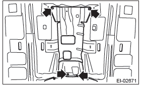
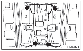
5) Remove the bolts to remove the front heat shield cover.
6) Remove the propeller shaft assembly.
CAUTION: Do not disassemble the propeller shaft.
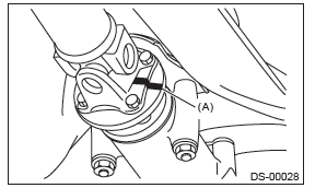
- Place alignment marks (A) on the flange yoke and rear differential.
- Remove four bolts holding the propeller shaft to the rear differential.
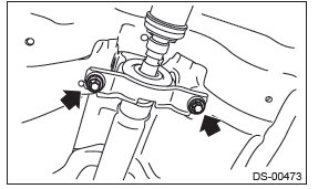
- Remove the center bearing.
- Remove the propeller shaft from transmission.
NOTE:
- Use a container to catch ATF or oil flowing from propeller shaft.
- To prevent ATF from leaking, install extension cap etc. to the transmission.
B: INSTALLATION
1) Before installation, check the following items, and replace the propeller shaft assembly as necessary.
- Dents or cracks on the tube surface
- Splines for deformation or abnormal wear
- Unsmooth joint operation or abnormal noise
- Center bearing for free play, noise or non-smooth operation.
- Oil seals for abnormal wear or damage
- Damaged center bearing
2) Insert the sleeve yoke into the transmission and attach center bearing to body.
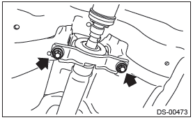
Tightening torque: 52 N*m (5.3 kgf-m, 38.4 ft-lb)
3) Align the alignment marks (A), and connect the flange yoke and rear differential.
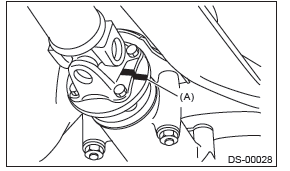
Tightening torque: 31 N*m (3.16 kgf-m, 22.9 ft-lb)
4) Check the propeller shaft with the propeller shaft installed to the vehicle. <Ref. to DS-12, INSPECTION, Propeller Shaft.>
5) Install the heat shield cover.
Tightening torque: 18 N*m (1.84 kgf-m, 13.3 ft-lb)
6) Install the center exhaust pipe and rear exhaust pipe.
7) Lower the vehicle.
C: INSPECTION
Check the propeller shaft with the propeller shaft installed to the vehicle.
1) Remove the front exhaust pipe.
- H4 turbo model: <Ref. to EX(H4DOTC)-5, REMOVAL, Front Exhaust Pipe.>
- H4 non-turbo model: <Ref. to EX(H4SO)-5, REMOVAL, Front Exhaust Pipe.>
- H6 model: <Ref. to EX(H6DO)-5, REMOVAL, Front Exhaust Pipe.>
2) Remove the center exhaust pipe, rear exhaust pipe, and muffler.
- Center exhaust pipe & rear exhaust pipe
- H4 turbo model: <Ref. to EX(H4DOTC)-15, REMOVAL, Rear Exhaust Pipe.>
- H4 non-turbo model: <Ref. to EX(H4SO)-9, REMOVAL, Rear Exhaust Pipe.>
- H6 model: <Ref. to EX(H6DO)-8, REMOVAL, Rear Exhaust Pipe.>
- Muffler
- H4 turbo model: <Ref. to EX(H4DOTC)-17, REMOVAL, Muffler.>
- H4 non-turbo model: <Ref. to EX(H4SO)-11, REMOVAL, Muffler.>
- H6 model: <Ref. to EX(H6DO)-10, REMOVAL, Muffler.>
3) Remove the bolts to remove the front heat shield cover.
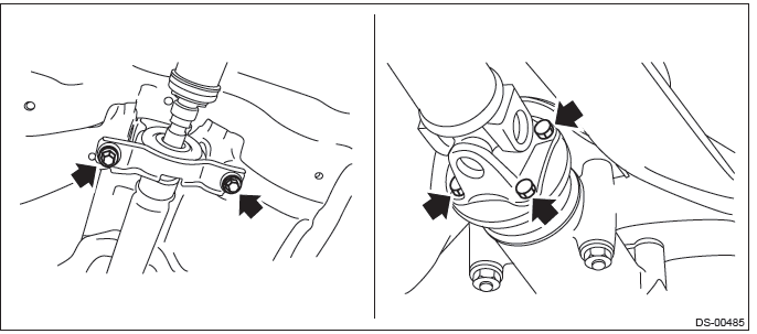
4) Check the propeller shaft mounting bolt for looseness.
- Yoke flange mounting bolts which connect to the rear differential
- Center bearing bracket mounting bolts
5) Check the spline and bearing for the propeller shaft.
- Turn the propeller shaft by hand to check if abnormal free play exists at splines.
- Also move yokes to check if abnormal free play exists at spiders and bearings.
6) Measure the deflection of the propeller shaft.
- Set the dial gauge (B) with its indicator stem at the center of the propeller shaft (A).
- Turn the propeller shaft (A) slowly by hands to check for runout of the propeller shaft.
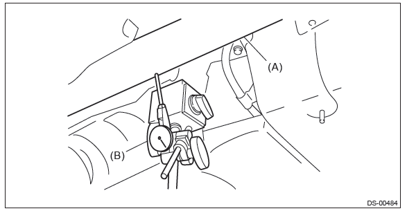
Runout: Limit: 0.6 mm (0.024 in)
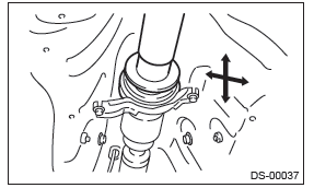
7) Check the center bearing for free play.
Move the propeller shaft near the center bearing up, down, left, right by hand, to check for any abnormal free play of the bearings.
8) Replace the propeller shaft assembly if faulty is found in the inspection.
READ NEXT:
 Front Axle
A: REMOVAL
1) Lift up the vehicle, and then remove the front wheels.
2) Remove the axle nut.
CAUTION:
Do not loosen the axle nut while the front axle is loaded. Doing so may damage
the hub bearing.
Front Hub Unit Bearing
A: REMOVAL
1) Lift up the vehicle, and then remove the front wheels.
2) Remove the axle nut.
CAUTION:
Do not loosen the axle nut while the front axle is loaded. Doing so may damage
the hub bearing.
Rear Axle
A: REMOVAL
1) Lift up the vehicle, and then remove the rear wheels.
2) Remove the axle nut.
CAUTION:
Do not loosen the axle nut while the rear axle is loaded. Doing so may damage
the hub bearing.
SEE MORE:
Tachometer
The tachometer shows the engine speed in thousands of revolutions per minute.
CAUTION
Do not operate the engine with the pointer of the tachometer in the red zone.
In this range, fuel injection will be cut by the engine control module to protect
the engine from overrevving. The engine will res
Continuously Variable Transmission Control Device
A: REMOVAL
1) Remove the transmission assembly from vehicle body. <Ref. to CVT-55, REMOVAL, Automatic Transmission Assembly.>
2) Remove the oil pan and control valve body. <Ref. to CVT-111, REMOVAL, Control Valve Body.>
3) Remove the inhibitor switch. <Ref. to CVT-98, REMOVAL, In
