Subaru Outback (BR): General Description of Starting-Charging Systems
Subaru Outback (BR) 2010-2015 Service Manual / Engine - H4SO / Starting/Charging Systems / General Description of Starting-Charging Systems
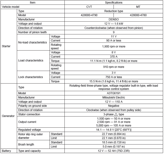
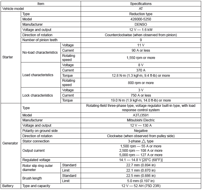
A: SPECIFICATION
1. 2.5 L MODEL
2. 3.6 L MODEL
B: COMPONENT
1. STARTER
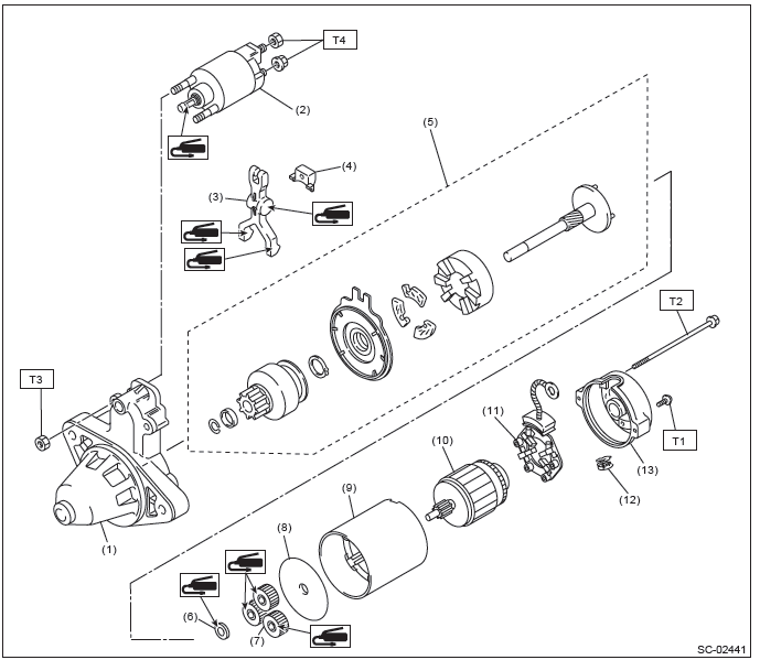
- Starter housing
- Magnet switch ASSY
- Shift lever
- Starter seal
- Overrunning clutch ASSY
- Washer
- Planetary gear
- Starter plate
- Yoke
- Armature
- Brush holder ASSY
- Drain duct
- Starter cover
Tightening torque: N*m (kgf-m, ft-lb)
T1: 1.4 (0.1, 1.0)
T2: 6 (0.6, 4.4)
T3: 7.5 (0.8, 5.5)
T4: 10 (1.0, 7.4)
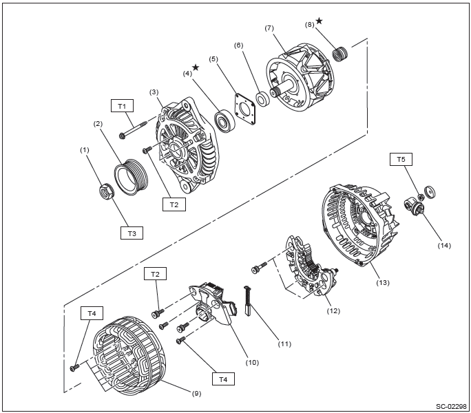
2. GENERATOR
- 2.5 L model
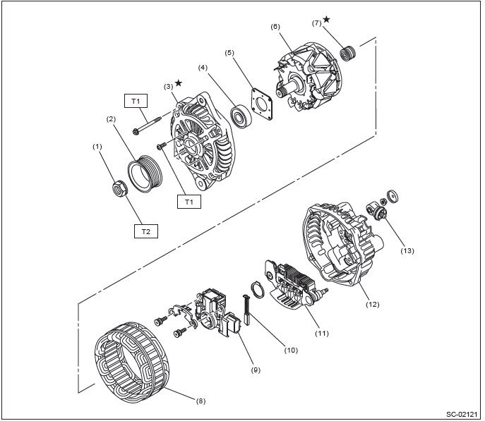
- Pulley nut
- Pulley
- Front cover
- Ball bearing
- Bearing retainer
- Rotor
- Bearing
- Stator coil
- IC regulator
- Brush
- Rectifier
- Rear cover
- Terminal B
Tightening torque: N*m (kgf-m, ft-lb)
T1: 4.7 (0.5, 3.5)
T2: 108 (11.0, 79.8)
- 3.6 L model
- Pulley nut
- Pulley
- Front cover
- Ball bearing
- Bearing retainer
- Spacer
- Rotor
- Bearing
- Stator coil
- IC regulator
- Brush
- Rectifier
- Rear cover
- Terminal B
Tightening torque: N*m (kgf-m, ft-lb)
T1: 4.4 (0.4, 3.2)
T2: 3.9 (0.4, 2.9)
T3: 117.5 (12.0, 86.7)
T4: 2 (0.2, 1.5)
T5: 8.9 (0.9, 6.6)
3. GENERATOR BRACKET
- 2.5 L model
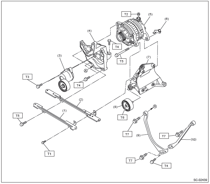
- V-belt cover bracket
- Collector cover bracket
- V-belt tensioner ASSY
- Power steering pump bracket
- Generator
- Generator plate
- A/C compressor bracket
- Idler pulley
- Stopper rod RH
- Stopper rod LH
Tightening torque: N*m (kgf-m, ft-lb)
T1: 6.4 (0.7, 4.7)
T2: 16 (1.6, 11.8)
T3: 20 (2.0, 14.8)
T4: 22 (2.2, 16.2)
T5: 25 (2.5, 18.4)
T6: 33 (3.4, 24.3)
T7: 36 (3.7, 26.6)
- 3.6 L model
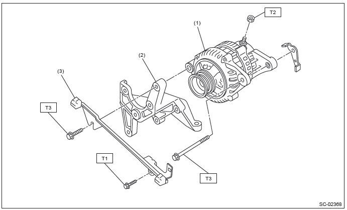
- Generator
- Power steering pump bracket
- Collector cover bracket
Tightening torque: N*m (kgf-m, ft-lb)
T1: 6.4 (0.7, 4.7)
T2: 16 (1.6, 11.8)
T3: 25 (2.5, 18.4)
C: CAUTION
- Wear appropriate work clothing, including a cap, protective goggles and protective shoes when performing any work.
- Remove contamination including dirt and corrosion before removal, installation or disassembly.
- Keep the disassembled parts in order and protect them from dust and dirt.
- Before removal, installation or disassembly, be sure to clarify the failure. Avoid unnecessary removal, installation, disassembly and replacement.
- Vehicle components are extremely hot after driving. Be wary of receiving burns from heated parts.
- Be sure to tighten fasteners including bolts and nuts to the specified torque.
- Place shop jacks or rigid racks at the specified points.
- Before disconnecting connectors of sensors or units, be sure to disconnect the ground cable from the battery.
D: PREPARATION TOOL
1. GENERAL TOOL

READ NEXT:
 Starter
A: REMOVAL
1) Disconnect the ground cable from battery.
2) Remove the cover (A) and clip (B) from air intake
boot assembly. (2.5 L non-turbo model)
3) Loosen the clamp (A) which connects the air int
Generator
A: REMOVAL
1) Disconnect the ground cable from battery.
2) Remove the V-belts. <Ref. to ME(H4SO)-43, VBELT,
REMOVAL, V-belt.> <Ref. to
ME(H4DOTC)-42, V-BELT, REMOVAL, V-belt.>
<Ref. t
Battery (inspection, removal, installation)
A: REMOVAL
1) After disconnecting the battery ground terminal, remove the terminal cover, then disconnect the positive terminal.
2) Remove the battery cable holder from the battery rod.
3) Remove
SEE MORE:
DTC P1152, P1153, P1160, P1443, P1492, P1493, P1494, P1495, P1496, P1497,
P1498, P1499, P1518, P1560, P1570, P1571, P1572, P1574, P1576, P1577, P1578
CZ:DTC P1152 O2 SENSOR CIRCUIT RANGE/PERFORMANCE (LOW) (BANK1
SENSOR1)
1. OUTLINE OF DIAGNOSIS
Detect that λ value remains low.
Judge as NG when lambda value is abnormal in accordance with λ value of front
oxygen (A/F) sensor and
running conditions such as vehicle speed, amount of intake
Rear view camera (if equipped)
Legacy
Outback
A rear view camera is attached to the trunk lid (Legacy) or rear gate (Outback).
When the ignition switch is “ON” and the shift lever (MT models) or select lever
(AT or CVT models) is set to “R”, the rear view camera automatically displays the
rear view image behin
© 2010-2026 Copyright www.suoutback.com
