Subaru Outback manuals

Subaru Outback (BR): Help line

The help line (distance marker and vehicle width line) is a guide to help you realize the actual distance from the screen.
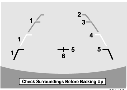
Help lines displayed on the navigation monitor
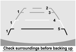

Help lines displayed on the navigation monitor

Help lines displayed on the inside mirror


Help lines displayed on the inside mirror

1) Vehicle width line (oblique vertical line) 2) Approx. 10 feet (3 m) from the bumper (green horizontal line) 3) Approx. 6.5 feet (2 m) from the bumper (green horizontal line) 4) Approx. 3 feet (1 m) from the bumper (yellow horizontal line) 5) Approx. 1.5 feet (0.5 m) from the bumper (red horizontal line) 6) Vehicle centerline

When the shift lever or select lever is set to position “R”, the monitor screen displays the help lines together with the rear view image.

CAUTION

● When moving backward, always check the back with your eyes without relying on the help lines.

● The actual position may be different from the indication of the help lines.

● Differences may occur due to number of passengers or loaded cargo.

● When the vehicle is on a slope or when the vehicle is inclined against the road, the indication is different from the actual position.

READ NEXT:

 Difference between screen and actual road

The distance markers show the distance for a level road when the vehicle is not loaded. It may be different from the actual distance depending on the loading conditions or road conditions. When t

 Feature of distance marker

1) 3 feet (1 m) line 2) 6.5 feet (2 m) line 3) 10 feet (3 m) line The distance marker shows the distance on the road. If there is a car or other object close behind, distance cannot be correctl

 Starting and operating

SEE MORE:

 Adverse safety consequences of overloading on handling and stopping and on tires

Overloading could affect vehicle handling, stopping distance, vehicle and tire as shown in the following. This could lead to an accident and possibly result in severe personal injury. ● Vehicle stability will deteriorate. ● Heavy and/or high-mounted loads could increase the risk of

 Stop Light Switch

A: REMOVAL 1) Disconnect the ground cable from battery. 2) Remove the instrument panel lower cover. Remove the clips, and remove the instrument panel side cover LH. Remove the clips and data link connector, and remove the instrument panel lower cover under. Remove the bolts, and remove

© 2010-2025 Copyright www.suoutback.com