Subaru Outback (BR): How to use Subaru Select Monitor, data, modes
A: OPERATION
1. HOW TO USE SUBARU SELECT MONITOR
NOTE:
- For detailed operation procedures, refer to "PC application help for Subaru Select Monitor".
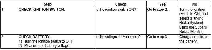
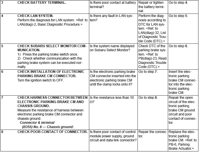
- If communication is not possible between the electronic parking brake control module and the Subaru Select Monitor, check the communication circuit. <Ref. to PB(diag)-21, COMMUNICATION FOR INITIALIZING IMPOSSIBLE, INSPECTION, Subaru Select Monitor.>
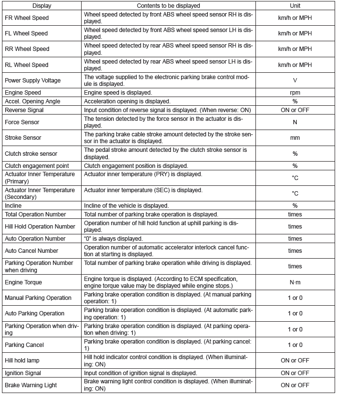
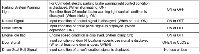
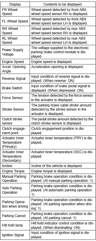
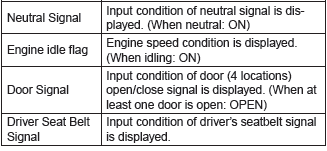
2. READ CURRENT DATA
NOTE:
- For detailed operation procedures, refer to "PC application help for Subaru Select Monitor".
- A list of the support data is shown in the following table.
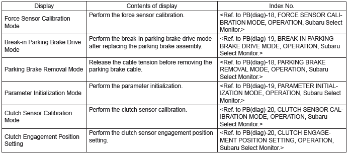
3. MAINTENANCE OPERATION MODE
4. FREEZE FRAME DATA
NOTE:
- Data stored at the time of trouble occurrence is shown on display.
- Each time a trouble occurs, the latest information is stored in the Freeze Frame Data in memory.
5. PARKING BRAKE REMOVAL MODE
CAUTION:
- Subaru Select Monitor is required for the parking brake removal mode.
- Make sure to perform this procedure with the vehicle lifted.
- When this mode is performed by mistake, operate and then release the parking brake.
NOTE: When disassembling the parking brake, use this function to set the parking brake cable at the release position.
1) Lift up the vehicle.
2) Connect the Subaru Select Monitor.
3) On "Main Menu" display, select {Each System Check}.
4) On "System Selection Menu" display, select {Brake Control System}.
5) Click the [OK] button after {Parking Brake System} is displayed.
6) On "Maintenance Operation Mode" display, select {Parking Brake Removal Mode}.
7) The confirmation screen, "Perform parking brake removal?", is displayed. Click the [YES] button.
8) The message, "Releasing parking cable until removal position.", is displayed on the screen, and the removal mode begins.
9) The message, "Parking cable released until removal position.", is displayed on the screen. Turn the ignition switch to OFF to end the removal mode.
6. FORCE SENSOR CALIBRATION MODE
CAUTION:
- Subaru Select Monitor is required for the Force Sensor Calibration Mode.
- Make sure to perform this procedure with the vehicle parked in a horizontal place and to use wheel chocks.
NOTE:
- When the following work is performed, use this function to perform calibration of force sensor in the parking brake actuator.
- Removing the parking brake assembly
- Replacing the electronic parking brake control module
- Adjusting the shoe clearance
- After replacing the electronic parking brake control module, if the calibration of the force sensor has not yet been performed, the brake warning light will blink and "Force Sensor Line (abnormal)" DTC will be detected.
1) Park the vehicle in a horizontal place using wheel chocks.
2) Connect the Subaru Select Monitor.
3) On "Main Menu" display, select {Each System Check}.
4) On "System Selection Menu" display, select {Brake Control System}.
5) Click the [OK] button after {Parking Brake System} is displayed.
6) On "Maintenance Operation Mode" display, select {Force Sensor Calibration Mode}.
7) The confirmation screen of vehicle parking condition and wheel chocks usage is displayed. Confirm the parking condition and wheel chocks, and click the [YES] button.
8) A message indicating the calibration mode in progress is displayed on the screen, and the Force Sensor Calibration Mode begins.
9) The message, "Force sensor calibration done.
Turn Ignition Switch OFF.", is displayed on the screen. Turn the ignition switch to OFF to end the calibration mode.
7. BREAK-IN PARKING BRAKE DRIVE MODE
CAUTION: Subaru Select Monitor is required for the "Break-in Parking Brake Drive Mode".
NOTE:
- When the parking brake shoe is replaced, use this function to perform parking brake lining breakin drive after adjusting the shoe clearance of the parking brake. <Ref. to PB-15, SHOE CLEARANCE, ADJUSTMENT, Parking Brake Assembly (Rear Disc Brake).>
- After performing the "Break-in Parking Brake Drive Mode", adjust the shoe clearance of the parking brake again, and perform the "Force Sensor Calibration Mode". <Ref. to PB(diag)-18, FORCE SENSOR CALIBRATION MODE, OPERATION, Subaru Select Monitor.>
1) Connect the Subaru Select Monitor.
2) On "Main Menu" display, select {Each System Check}.
3) On "System Selection Menu" display, select {Brake Control System}.
4) Click the [OK] button after {Parking Brake System} is displayed.
5) On "Maintenance Operation Mode" display, select {Break-in Parking Brake Drive Mode}.
6) The confirmation message, "Perform break-in parking brake drive?", is displayed on the screen.
With the vehicle parked, release the parking brake, and click the [YES] button.
7) Confirm the message indicating the break-in drive mode start on the screen and the blink of the brake warning light, and begin the break-in drive.
8) Drive the vehicle at approximately 35 km/h (22 MPH) or more.
9) C6 model Drive the vehicle approximately 200 m (0.12 miles) with the parking brake switch pressed, until the brake warning light goes off.
10) Models other than C6 model Drive the vehicle approximately 200 m (0.12 miles) with the parking brake switch pressed. Release a hand from the parking brake switch once to cancel.
Drive the vehicle again with the parking brake switch pressed, and if brake drag is not felt, go to step 11). If brake drag is felt, repeat steps 8) and 10) again.
11) Turn the ignition switch to OFF, and wait for 5 to 10 minutes until the parking brake temperature drops.
12) Repeat steps 2) to 10) again.
13) Turn the ignition switch to OFF to end the break-in drive mode.
14) Adjust the shoe clearance of the parking brake again. <Ref. to PB-15, SHOE CLEARANCE, ADJUSTMENT, Parking Brake Assembly (Rear Disc Brake).>
15) Perform the Force Sensor Calibration Mode.
<Ref. to PB(diag)-18, FORCE SENSOR CALIBRATION MODE, OPERATION, Subaru Select Monitor.>
8. PARAMETER INITIALIZATION MODE
CAUTION:
- Subaru Select Monitor is required for the Parameter Initialization Mode.
- This function can be used for replacement parts of the electronic parking brake control module.
NOTE:
- When DTC "Parameter selection error" is detected after replacing the electronic parking brake control module, use this function to perform parameter initialization of the electronic parking brake control module.
- After performing Parameter Initialization Mode, perform the Force Sensor Calibration Mode and Clutch Sensor Calibration Mode. <Ref. to PB(diag)- 18, FORCE SENSOR CALIBRATION MODE, OPERATION, Subaru Select Monitor.> <Ref. to PB(diag)- 20, CLUTCH SENSOR CALIBRATION MODE, OPERATION, Subaru Select Monitor.>
1) Connect the Subaru Select Monitor.
2) On "Main Menu" display, select {Each System Check}.
3) On "System Selection Menu" display, select {Brake Control System}.
4) Click the [OK] button after {Parking Brake System} is displayed.
5) On "Maintenance Operation Mode" display, select {Parameter Initialization Mode}.
6) The confirmation message, "Perform parameter initialization?", is displayed on the screen. Following the instructions on the screen, confirm the connections of all control modules, and click the [YES] button.
7) The message, "Parameter initialization in progress...", is displayed on the screen, and initialization begins.
8) The message, "Parameter initialization done.. Turn Ignition Switch OFF.", is displayed on the screen. Turn the ignition switch to OFF to end the Parameter Initialization Mode.
9. CLUTCH SENSOR CALIBRATION MODE
CAUTION: Subaru Select Monitor is required for Clutch Sensor Calibration Mode.
NOTE:
- When the following parts are replaced, use this function to perform clutch sensor calibration.
- Clutch master cylinder assembly
- Electronic parking brake control module
- Clutch pedal
- After replacing the parts above, if the calibration of the clutch sensor has not yet been performed, "Clutch Sensor" DTC will be detected. At this time, the electronic parking brake warning light illuminates on C6 model, or the brake warning light blinks on models other than C6 model.
1) Connect the Subaru Select Monitor.
2) On "Main Menu" display, select {Each System Check}.
3) On "System Selection Menu" display, select {Brake Control System}.
4) Click the [OK] button after {Parking Brake System} is displayed.
5) On "Maintenance Operation Mode" display, select {Clutch Sensor Calibration Mode}.
6) The confirmation message, "Perform clutch sensor calibration?", is displayed on the screen. Following the instructions on the screen, click the [YES] button with the clutch pedal not depressed.
7) The message, "Clutch sensor calibration done. Turn Ignition switch OFF.", is displayed on the screen. Turn the ignition switch to OFF to end the calibration mode.
10.CLUTCH ENGAGEMENT POSITION SETTING
CAUTION: Subaru Select Monitor is required for Clutch Engagement Position Setting.
NOTE:
- When the clutch master cylinder assembly is replaced, use this function to set the engagement position for the clutch stroke sensor.
- When the customer requested a change of the accelerator interlocking release timing, use this function to change the engagement position of the clutch stroke sensor in order to change the accelerator interlocking release timing.
- The clutch engagement position can be set between 50 - 80%.
1) Park the vehicle on a safe level surface without obstacles.
2) Start the engine to warm up.
3) Connect the Subaru Select Monitor.
4) On "Main Menu" display, select {Each System Check}.
5) On "System Selection Menu" display, select {Brake Control System}.
6) Click the [OK] button after {Parking Brake System} is displayed.
7) On "Maintenance Operation Mode" display, select {Clutch Engagement Position Setting}.
8) Release the parking brake. Shift the gear to 1st, then slowly release the clutch pedal, and read "Clutch position current value" on the screen when the vehicle starts to move.
9) Enter the reading to "Engagement position input value", and press the [Execution] button.
10) Turn the ignition switch to OFF to end the clutch engagement position setting.
11) Drive the vehicle, and check the accelerator interlocking release timing.
CAUTION: If the clutch engagement position is not set correctly, early release or release delay of the parking brake may occur at the accelerator interlocking release. After completing the setting, check the accelerator interlocking timing in a safe place, and confirm that neither early release nor release delay occurs.
NOTE:
- When a smaller value than "Engagement position learning value" is entered in "Engagement position input value", the parking brake release timing delays.
- When a larger value than "Engagement position learning value" is entered in "Engagement position input value", the parking brake release timing becomes early.
B: INSPECTION
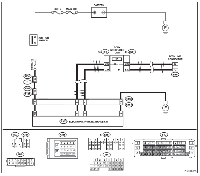
1. COMMUNICATION FOR INITIALIZING IMPOSSIBLE
DETECTING CONDITION:
Defective harness connector
TROUBLE SYMPTOM:
Communication is impossible between the electronic parking brake control module and Subaru Select Monitor.
WIRING DIAGRAM:
READ NEXT:
 Read Diagnostic Trouble
Code (DTC)
Read Diagnostic Trouble
Code (DTC)
A: OPERATION
NOTE:
For detailed operation procedures, refer to "PC
application help for Subaru Select Monitor".
For details concerning DTCs, refer to "List of Diagnostic
Trouble Code (DTC)". <
Parking Brake - List of Diagnostic Trouble Code (DTC)
A: LIST
Diagnostic Procedure with Diagnostic Trouble Code (DTC)
A: DTC C0221 PARKING POSITION SWITCH
DTC DETECTING CONDITION:
Defective parking brake switch
Defective harness connec
SEE MORE:
Tips for the Hands-free system
Bluetooth®
NOTE
The Bluetooth word mark and logo are registered trademarks of Bluetooth SIG,
Inc.
It is possible to connect a cell phone to the in-vehicle equipment through the
Bluetooth ® format (wireless) to make a phone call from the in-vehicle equipment
or take an incoming phone call.
Vehicle Dynamics Control operation indicator light
The indicator light flashes during activation of the skid suppression function
and during activation of the traction control function.
NOTE
● The light may remain illuminated for a short period of time after the engine
has been started, especially in cold weather. This does not indicate
