Subaru Outback (BR): Keyless Entry Control Module
A: REMOVAL
1. SEDAN MODEL
1) Disconnect the ground cable from battery.
2) Remove the rear shelf trim. <Ref. to EI-120, REMOVAL, Rear Shelf Trim.>
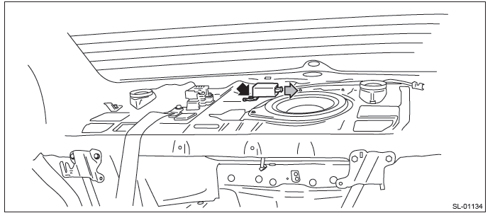
3) Remove the keyless entry control module.
- Disconnect the connector.
- Remove the bolt and remove the keyless entry control module.
2. OUTBACK MODEL
1) Disconnect the ground cable from battery.
2) Remove the rear quarter trim LH. <Ref. to EI-110, REMOVAL, Rear Quarter Trim.>
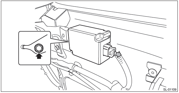
3) Remove the keyless entry control module.
- Disconnect the connector.
- Remove the bolt and remove the keyless entry control module.
B: INSTALLATION
Install each part in the reverse order of removal.
Tightening torque:
Keyless entry control module: 7.5 N*m (0.76 kgf-m, 5.5 ft-lb)
Keyless Buzzer
A: REMOVAL
1) Disconnect the ground cable from battery.
2) Remove the front bumper face. <Ref. to EI-39, REMOVAL, Front Bumper.>
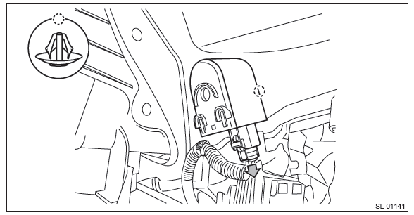
3) Remove the keyless buzzer.
- Disconnect the connector.
- Remove the clip, and remove the keyless buzzer.
B: INSTALLATION
1) Install each part in the reverse order of removal.
2) Adjust the fog light beam. (Model with fog light) <Ref. to LI-41, FOG LIGHT AIMING, ADJUSTMENT, Front Fog Light Assembly.>
C: INSPECTION
1) Using the Subaru Select Monitor, perform forced operation of the keyless buzzer. <Ref. to BC(diag)-16, OPERATION, User Customizing.>
2) If the buzzer does not sound, replace the keyless buzzer.
Body Integrated Unit
A: NOTE
1. WHEN REPLACING THE BODY INTEGRATED UNIT
1) Check and record the current setting. <Ref. to BC(diag)-18, CONFIRM CURRENT SETTING., OPERATION, Registration Body Integrated Unit.>
2) Prepare the following.
- Security ID plate
- Required number of registered immobilizer keys or new (not registered) immobilizer keys.
2. AFTER REPLACING THE BODY INTEGRATED UNIT
1) Register the immobilizer. For detailed operation procedures, refer to "PC application help for Subaru Select Monitor".
2) Set the current settings as recorded.
B: REMOVAL
1) Disconnect the ground cable from battery.
2) Remove the instrument panel lower cover. <Ref. to EI-64, REMOVAL, Instrument Panel Lower Cover.>
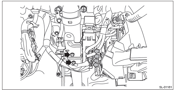
3) Remove the body integrated unit.
CAUTION: Be careful to keep water and other foreign materials away from body integrated unit.
- Remove the harness clip and connector.
- Remove the bolts, and remove the body integrated unit.
C: INSTALLATION
Install each part in the reverse order of removal.
Tightening torque:
Body integrated unit: 7.5 N*m (0.76 kgf-m, 5.5 ft-lb)
NOTE: Make sure that there are no differences from the contents of the current settings after installation. <Ref. to BC(diag)-12, LIST, Read Current Data.>
READ NEXT:
 Keyless Transmitter
A: REMOVAL
NOTE:
For C6 model, refer to Transmitter. <Ref. to SL-75, REMOVAL, Transmitter.>
1. KEYLESS TRANSMITTER BATTERY
CAUTION:
To prevent static electricity damage to the keyless transmitte
Sunroof/T-Top/Convertible Top (Sunroof)
General Description
A: COMPONENT
Glass lid
Weather strip
Lid cover
Sunshade
Drain tube
Motor ASSY
Frame ASSY
Deflector
Drain plate
Stopper rubber
Link ASSY
Lid bracket
Tightening torque
SEE MORE:
Side mirrors
After hitching a trailer to your vehicle, check that the standard side mirrors provide a good rearward field of view without significant blind spots. If significant blind spots occur with the vehicle’s standard side mirrors, use towing mirrors that conform with Federal, state/prov
Precaution, Identification, Recommended Materials
Precaution
A: CAUTION
Please clearly understand and adhere to the following
general precautions. They must be strictly followed
to avoid minor or serious injury to the person
doing the work or people in the area.
1. VEHICLE DYNAMICS CONTROL (VDC)
Handle the VDC as a total system. Do not disassemble
