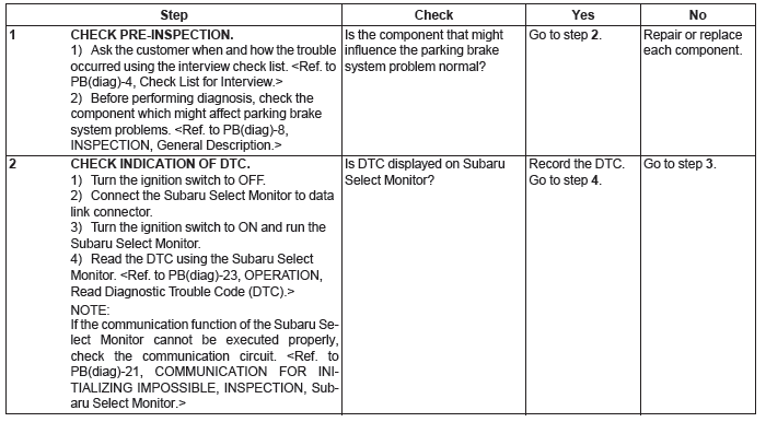
Subaru Outback (BR): Basic Diagnostic Procedure of Parking Brake
A: PROCEDURE
CAUTION: When removing or installing, remove all foreign matter (dust, water, and oil) from the electronic parking brake control module connectors.
NOTE:
- To check the harness for open or short circuits, shake problem spot or connector.
- Refer to "Check List for Interview". <Ref. to PB(diag)-4, Check List for Interview.>
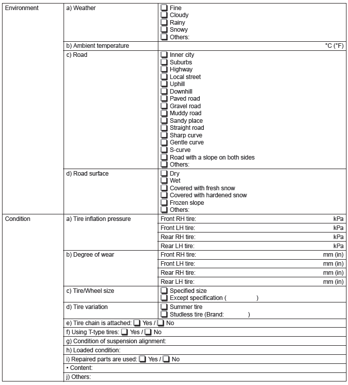
Check List for Interview
A: CHECK
Check the following item about the vehicle's state.
1. STATE OF BRAKE WARNING LIGHT
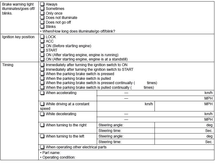
2. STATE OF ELECTRONIC PARKING BRAKE WARNING LIGHT (C6 MODEL ONLY)
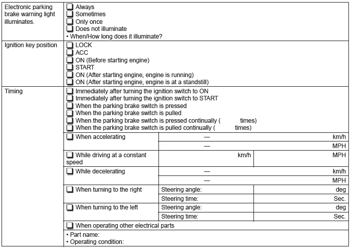
3. HILL HOLD INDICATOR LIGHT CONDITION
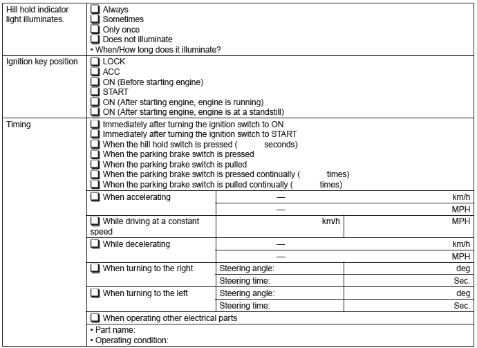
4. CONDITIONS UNDER WHICH TROUBLE OCCURS
General Description
A: CAUTION
1. SUPPLEMENTAL RESTRAINT SYSTEM "AIRBAG"
Airbag system wiring harness is routed near the parking brake switch, hill hold switch and electronic parking brake control module.
CAUTION:
- Do not use electrical test equipment on the airbag system circuits.
- Be careful not to damage the airbag system wiring harness, when servicing the parking brake switch, hill hold switch and electronic parking brake control module.
B: INSPECTION
Before performing diagnosis, inspect the following items which may influence parking brake system problems.
1. BATTERY
Measure the battery voltage and specific gravity of the electrolyte.
Standard voltage: 12 V or more
Specific gravity: 1.260 or more
2. GROUND
Check the tightening torque of ground (GB-9 and 10) bolts of the parking brake system.
Tightening torque: 13 N*m (1.3 kgf-m, 9.6 ft-lb)
3. BRAKE DRAG
Check for brake drag.
4. PARKING BRAKE ASSEMBLY
Check and adjust the parking brake assembly.
- Check the disc rotor inner diameter and lining thickness. <Ref. to PB-15, INSPECTION, Parking Brake Assembly (Rear Disc Brake).>
- Adjust the shoe clearance. <Ref. to PB-15, ADJUSTMENT, Parking Brake Assembly (Rear Disc Brake).>
5. TIRE
Check the tire specifications, tire wear and air pressure.
<Ref. to WT-2, SPECIFICATION, General Description.>
C: PREPARATION TOOL
1. SPECIAL TOOL
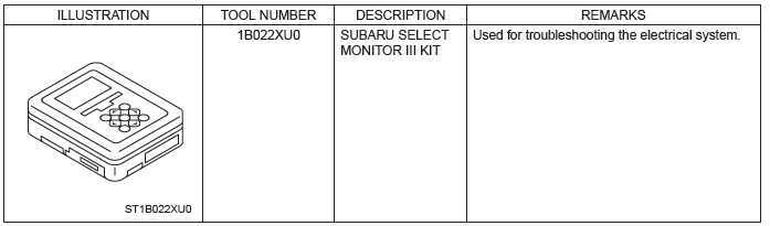
2. GENERAL TOOL

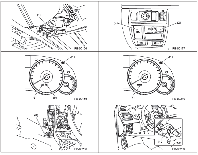
Electrical Component Location
A: LOCATION
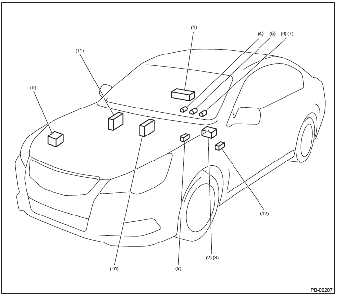
- Electronic parking brake control module
- Parking brake switch
- Hill hold switch
- Hill hold indicator light
- Electronic parking brake warning light (C6 model only)
- Brake warning light (C0, C5 and C6 models)
- Brake warning light (U4, U5 and U6 models)
- Clutch stroke sensor (MT model only)
- VDC control module and hydraulic control unit (VDCCM&H/U)
- Body integrated unit
- Engine control module (ECM)
- Data link connector
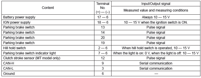
Control Module I/O Signal
A: ELECTRICAL SPECIFICATION
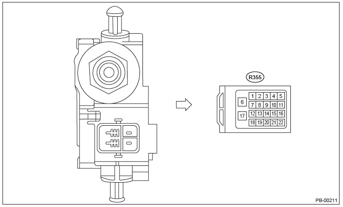
NOTE: The terminal numbers of the electronic parking brake control module connectors are as indicated in the figure.
B: WIRING DIAGRAM
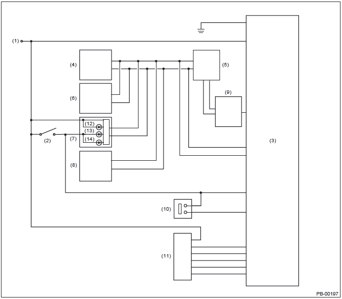
- Battery
- Ignition switch
- Electronic parking brake CM
- Engine control module (ECM)
- VDC control module
- Transmission control module
- Combination meter
- Body integrated unit
- Clutch stroke sensor (MT model only)
- Hill hold switch
- Parking brake switch
- Hill hold indicator light
- Electronic parking brake warning light (C6 model only)
- Brake warning light
READ NEXT:
 How to use Subaru Select Monitor, data, modes
A: OPERATION
1. HOW TO USE SUBARU SELECT MONITOR
NOTE:
For detailed operation procedures, refer to "PC application help for Subaru Select Monitor".
If communication is not pos
Read Diagnostic Trouble
Code (DTC)
A: OPERATION
NOTE:
For detailed operation procedures, refer to "PC
application help for Subaru Select Monitor".
For details concerning DTCs, refer to "List of Diagnostic
Trouble Code (DTC)". <
Parking Brake - List of Diagnostic Trouble Code (DTC)
A: LIST
Diagnostic Procedure with Diagnostic Trouble Code (DTC)
A: DTC C0221 PARKING POSITION SWITCH
DTC DETECTING CONDITION:
Defective parking brake switch
Defective harness connec
SEE MORE:
Fuses
CAUTION
Never replace a fuse with one having a higher rating or with material other than
a fuse because serious damage or a fire could result.
The fuses are designed to melt during an overload to prevent damage to the wiring
harness and electrical equipment. The fuses are located in two fuse b
Rear Quarter Trim
A: REMOVAL
1. SEDAN MODEL
1) Disconnect the ground cable from battery and wait for at least 60 seconds
before starting work.
CAUTION:
The airbag system is fitted with a backup power supply. After disconnecting the
battery ground cable,
the airbag may operate if you do not wait for 60 seconds befor
