Subaru Outback (BR): General Description of Front Suspension
Subaru Outback (BR) 2010-2015 Service Manual / Chassis / Front Suspension / General Description of Front Suspension
A: SPECIFICATION
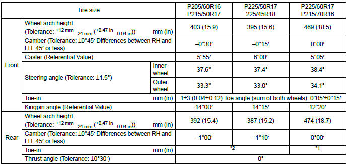
*1: OUTBACK model
2+-3 mm (0.08 - 0.12 in) Toe angle (sum of both wheels): 0º10′+-0º15′
*2: Except for OUTBACK model
0+-3 mm (0+-0.12 in) Toe angle (sum of both wheels): 0º+-0º15′
NOTE:
- Front and rear toe-in and front camber can be adjusted. Adjust if the toe-in or camber tolerance exceeds specifications.
- Other items indicated in the specifications is not equipped with adjustment mechanisms. If other items exceed specifications, check the suspension parts and connections for deformation. If defective, replace with new parts.
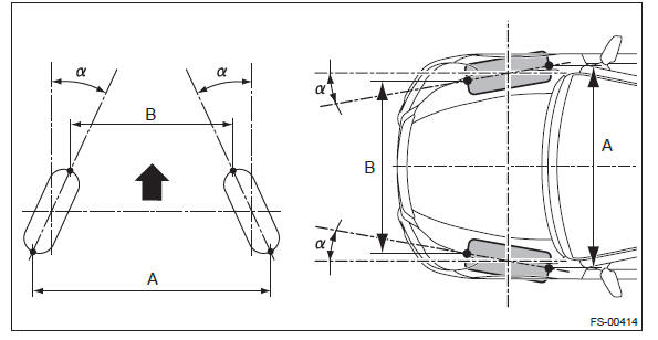
A - B = Positive: Toe-in, Negative: Toe-out
α = Individual toe angles
B: COMPONENT
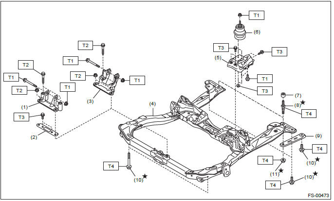
- Front mounting bracket (H6 model)
- Bracket
- Front mounting bracket (H4 model)
- Cradle
- Main mounting bracket
- Main cushion rubber
- Stopper (OUTBACK model only)
- Stud bolt
- Stiffener
- Bolt
- Self-locking nut
Tightening torque: N*m (kgf-m, ft-lb)
T1: 45 (4.59, 33.2)
T2: 60 (6.12, 44.3)
T3: 65 (6.63, 47.9)
T4: 75 (7.65, 55.3)
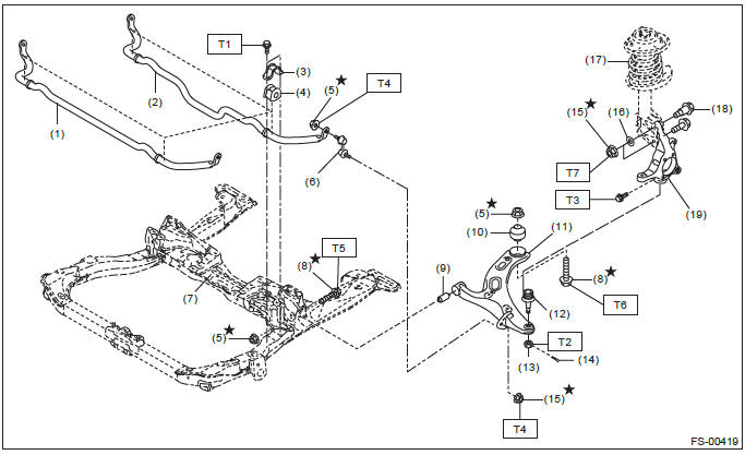
- Stabilizer (H6 model)
- Stabilizer (H4 model)
- Stabilizer bracket
- Stabilizer bushing
- Self-locking nut
- Stabilizer link
- Cradle
- Bolt
- Front bushing
- Rear bushing
- Front arm
- Ball joint
- Castle nut
- Cotter pin
- Flange nut
- Adjusting washer
- Front strut ASSY
- Adjusting bolt
- Front axle housing
Tightening torque: N*m (kgf-m, ft-lb)
T1: 25 (2.55, 18.4)
T2: 39 (3.98, 28.8)
T3: 50 (5.10, 36.9)
T4: 60 (6.12, 44.3)
T5: 95 (9.69, 70.1)
T6: 140 (14.28, 103.3)
T7: 155 (15.81, 114.3)
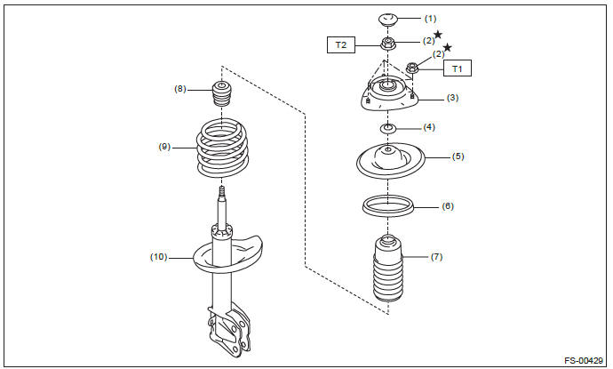
- Dust seal
- Self-locking nut
- Strut mount
- Spacer
- Upper spring seat
- Rubber seat (OUTBACK model only)
- Dust cover
- Helper (except for Bilstein strut)
- Coil spring
- Strut
Tightening torque: N*m (kgf-m, ft-lb)
T1: 20 (2.04, 14.8)
T2: 55 (5.61, 40.6)
C: CAUTION
- Wear appropriate work clothing, including a helmet, protective goggles and protective shoes when performing any work.
- Before removal, installation or disassembly, be sure to clarify the failure. Avoid unnecessary removal, installation, disassembly and replacement.
- Use SUBARU genuine grease etc. or equivalent. Do not mix grease etc. of different grades or manufacturers.
- Before securing a part on a vise, place cushioning material such as wood blocks, aluminum plate, or cloth between the part and the vise.
- Be sure to tighten fasteners including bolts and nuts to the specified torque.
- Place shop jacks or rigid racks at the specified points.
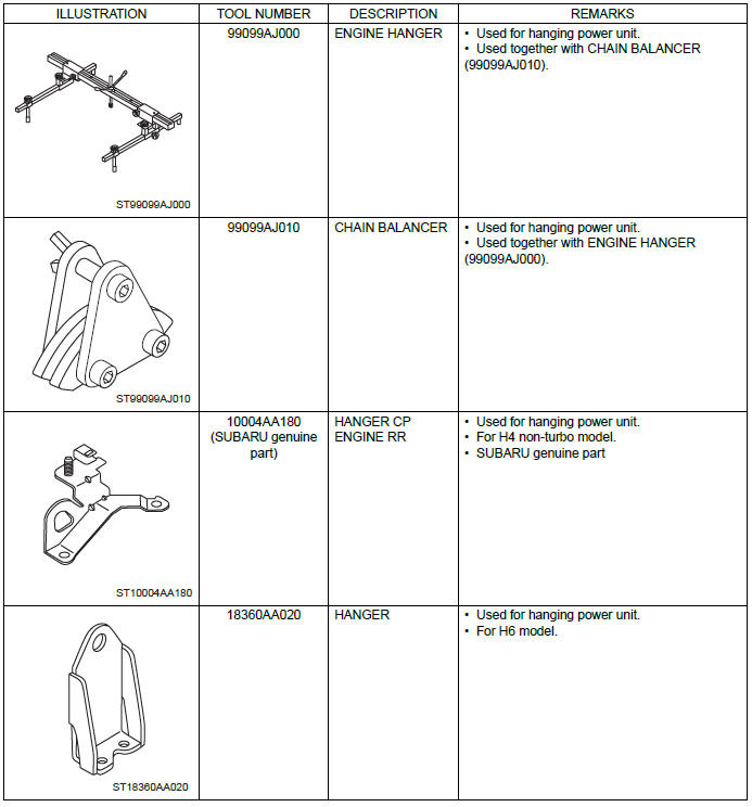
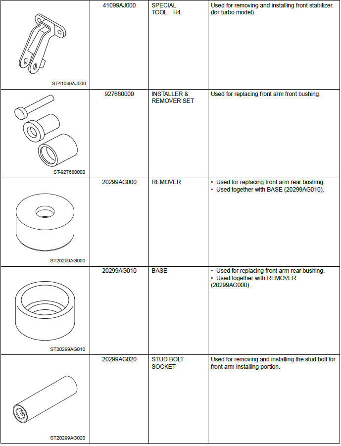
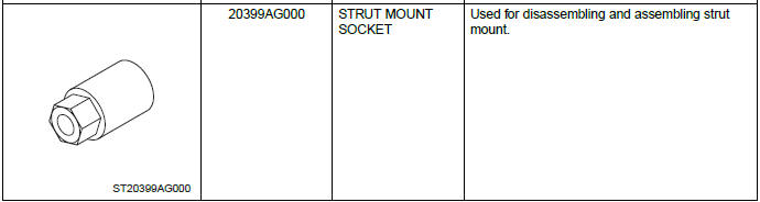
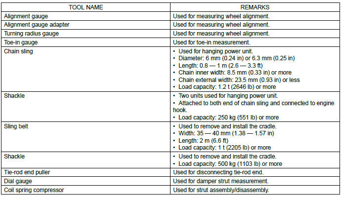
D: PREPARATION TOOL
1. SPECIAL TOOL
2. GENERAL TOOL
READ NEXT:
 Wheel Alignment (inspection, adjustment)
A: INSPECTION
Check the following items before performing the wheel alignment measurement.
Tire inflation pressure
Uneven wear of RH and LH tires, or difference of sizes
Tire runout
Cradle
A: REMOVAL
1) Set the vehicle on a lift.
2) Adjust the tilt position of the steering column to the lowest position and
lock the tilt lever.
3) Prevent the steering wheel from turning using the seat
Front Stabilizer
A: REMOVAL
1) Lift up the vehicle, and then remove the left and right front wheels.
2) Remove the front under cover. <Ref. to EI-35, REMOVAL, Front Under Cover.>
3) Remove the center exhaust p
SEE MORE:
CVTF
A: INSPECTION
Check for leakage of CVTF from transmission.
B: ADJUSTMENT
CAUTION:
CVTF level changes along with CVTF temperature. When inspecting CVTF
level, observe the specified
CVTF temperature.
Always use specified CVTF or equivalent. Using other fluid than
specified or equivalent will c
Engine oil
NOTE
● When the engine low oil level warning light illuminates, have your vehicle
inspected by your SUBARU dealer as soon as possible.
● The engine oil consumption rate is not stabilized, and therefore cannot be
determined until the vehicle has traveled at least several thousand
© 2010-2026 Copyright www.suoutback.com
