Subaru Outback (BR): Wheel Alignment (inspection, adjustment)
A: INSPECTION
Check the following items before performing the wheel alignment measurement.
- Tire inflation pressure
- Uneven wear of RH and LH tires, or difference of sizes
- Tire runout
- Excessive play and wear of ball joint
- Excessive play and wear of tie-rod end
- Excessive play of wheel bearing
- Right and left wheel base imbalance
- Deformation and excessive play of steering link
- Deformation and excessive play of suspension parts
Check, adjust and measure the wheel alignment in accordance with the following procedures.
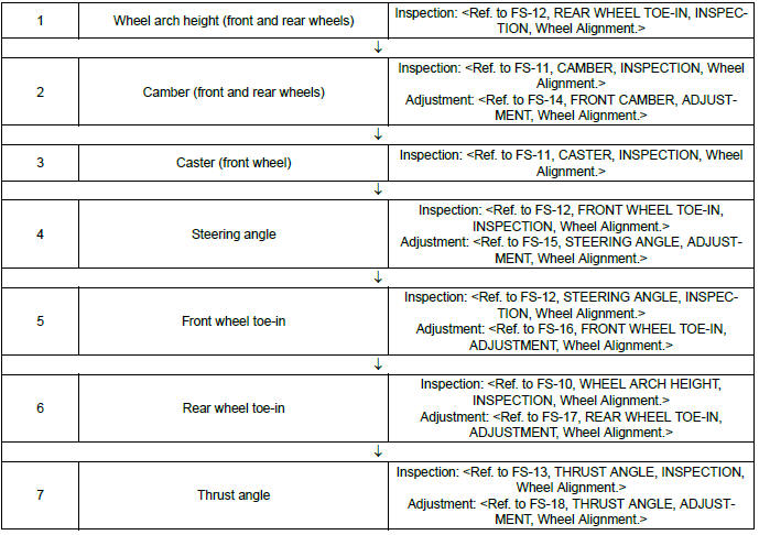
1. WHEEL ARCH HEIGHT
1) Park the vehicle on a level surface.
2) Empty the vehicle so that it is at "curb weight". (Empty the luggage compartment, load the spare tire, jack and service tools, and fill up the fuel tank.)
3) Set the steering wheel in a straight-ahead position, and stabilize the suspension by moving the vehicle in a straight line for 5 m (16 ft) or more.
4) Suspend a thread from the wheel arch (point "A" in the figure below) and affix at a position directly above the center of wheel.
5) Measure the distance between the point "A" and the center of wheel.
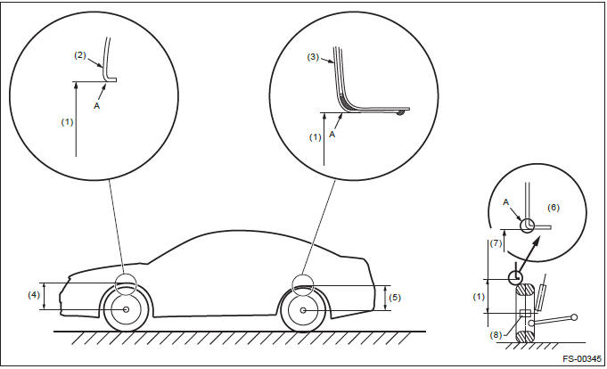
- Wheel arch height
- Front fender
- Rear quarter
- Front wheel arch height
- Rear wheel arch height
- Flange bend line
- Point of measurement
- End of spindle
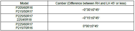
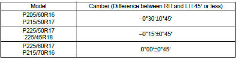
2. CAMBER
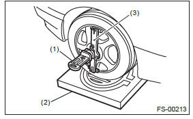
1) Place the front wheel on the turning radius gauge.
NOTE: Make sure the ground contact surfaces of the front and rear wheels are at the same height.
2) Set the adapter into the center of wheel, and then set the wheel alignment gauge.
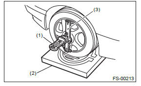
- Alignment gauge
- Turning radius gauge
- Adapter
3) Measure the camber angle in accordance with the operation manual for wheel alignment gauge.
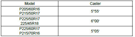
3. CASTER
1) Place the front wheel on the turning radius gauge. Make sure the ground contact surfaces of the front and rear wheels are at the same height.
2) Set the adapter into the center of wheel, and then set the wheel alignment gauge.
- Alignment gauge
- Turning radius gauge
- Adapter
3) Measure the caster angle in accordance with the operation manual for wheel alignment gauge.
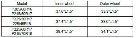
4. STEERING ANGLE
1) Place the vehicle on turning radius gauge.
2) While depressing the brake pedal, turn the steering wheel fully to the left and right.
3) With the steering wheel held at each fully turned position, measure both the inner and outer wheel steering angles.
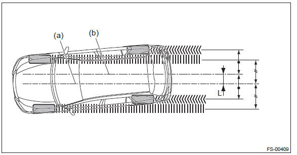
5. FRONT WHEEL TOE-IN
Toe-in: Inspection value 1+-3 mm (0.04+-0.12 in)
1) Set the toe-in gauge in the position at wheel axis center height behind the right and left front tires.
2) Place a mark at the center of both left and right tires, and measure distance "A" between the marks.
3) Move the vehicle forward to rotate the tires 180º.
NOTE: Be sure to rotate the tires in the forward direction.
4) Measure the distance "B" between the left and right marks. Find toe-in using the following calculation:
A - B = Toe-in
6. REAR WHEEL TOE-IN
Refer to the FRONT WHEEL TOE-IN for rear toe-in inspection procedures. <Ref. to FS-12, STEERING ANGLE, INSPECTION, Wheel Alignment.>
Toe-in: Inspection value
Other than OUTBACK model: 0+-3 mm (0+-0.12 in)
OUTBACK model: 2+-3 mm (0.08+-0.12 in)
7. THRUST ANGLE
1) Park the vehicle on a level surface.
2) Move the vehicle 3 to 4 meters (10 to 13 feet) straight forward.
3) Draw the center of loci for both the front and rear axles.
4) Measure distance "L" between the center lines of the axle loci.
Thrust angle: Inspection value
0º+-30′
Less than 30′ when "L" is 23 mm (0.9 in) or less
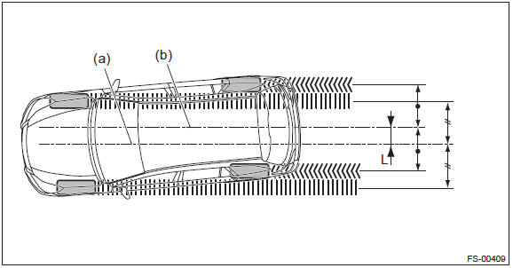
- Center line of loci (front axle)
- Center line of loci (rear axle)
B: ADJUSTMENT
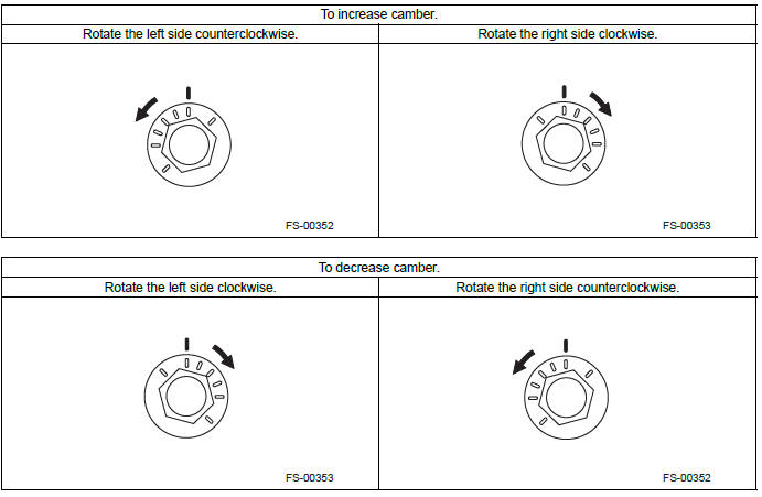
1. FRONT CAMBER
1) Adjust the camber angle to the following value.
2) Loosen the two flange nuts located at the front lower section of the strut.
NOTE: When the adjusting bolt needs to be loosened or tightened, hold its head with a wrench and turn the flange nut.
3) Turn the camber adjusting bolt so that the camber is set at specification.
NOTE: Moving the adjusting bolt by one scale changes the camber by approximately 0º15′.
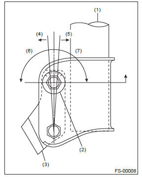
- Strut
- Adjusting bolt
- Front axle housing
- Outer
- Inner
- Camber is increased.
- Camber is decreased.
4) Tighten two new flange nuts.
Tightening torque: 155 N*m (15.81 kgf-m, 114.3 ft-lb)
2. STEERING ANGLE
1) Adjust the steering angle of both inner and outer wheels.
- Loosen the steering tie-rod lock nut (a), and rotate the tie-rod.
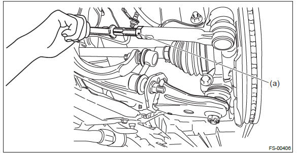
- Turn the tie-rod to adjust the steering angle of both inner and outer wheels.
- Tighten the steering tie-rod lock nut (a).
Tightening torque: 85 N*m (8.67 kgf-m, 62.7 ft-lb)
NOTE: Check and correct the tie-rod boot if twisted.
2) Check the toe-in. <Ref. to FS-12, STEERING ANGLE, INSPECTION, Wheel Alignment.>
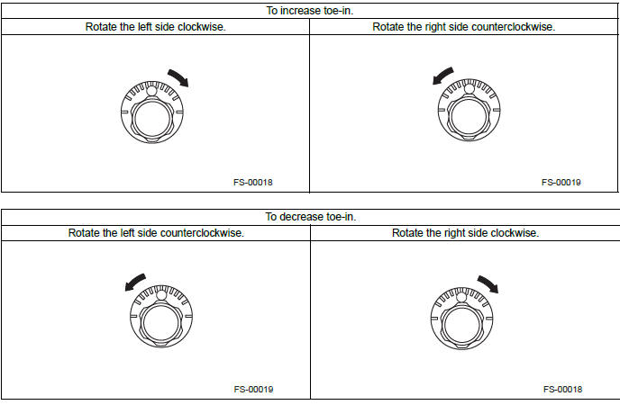
3. FRONT WHEEL TOE-IN
When adjusting the toe-in, adjust it to the following value. <Ref. to FS-15, STEERING ANGLE, ADJUSTMENT, Wheel Alignment.>
Toe-in: Adjustment value 1+-2 mm (0.04+-0.08 in)
1) Check that the left and right wheel steering angles are within specification.
2) Loosen the left and right side steering tie-rod lock nuts (a).
3) Turn the left and right tie-rods by equal amounts until the toe-in is at the specification.
NOTE: Both the left and right tie-rods are right-hand threaded. To increase toe-in, turn both tie-rods clockwise by equal amount (viewing from the inside of vehicle).
4) Tighten the tie-rod lock nut.
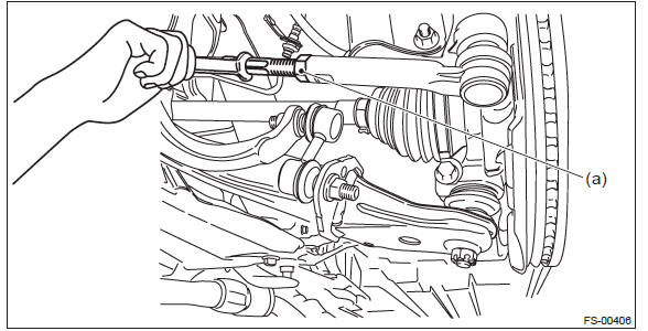
Tightening torque: 85 N*m (8.67 kgf-m, 62.7 ft-lb)
5) Check and correct the tie-rod boot if twisted.
4. REAR WHEEL TOE-IN
When adjusting, adjust it to the following value.
Toe-in: Adjustment value
Other than OUTBACK model: 0+-2 mm (0+-0.08 in)
OUTBACK model: 2+-2 mm (0.08+-0.08 in)
1) Loosen the self-locking nut for the front lateral link.
NOTE: When loosening or tightening the adjusting bolt, hold the bolt head and turn the self-locking nut.
- Adjusting bolt
- Lateral link
2) Turn the adjusting bolt until toe-in is within the specification.
NOTE: When the left and right wheels are adjusted for toe-in at the same time, the movement of one scale graduation changes toe-in by approx. 1.3 mm (0.05 in).
3) Attach and tighten a new self-locking nut.
Tightening torque: 120 N*m (12.24 kgf-m, 88.5 ft-lb)
5. THRUST ANGLE
When adjusting, adjust it to the following value.
Thrust angle: Adjustment value
0º+-20′
Less than 20′ when "L" is 15 mm (0.6 in) or less
- Center line of loci (front axle)
- Center line of loci (rear axle)
1) Make thrust angle adjustments by turning the toe-in adjusting bolts of the rear suspension equally in the same direction.
2) When one rear wheel is adjusted in a toe-in direction, adjust the other rear wheel equally in toe-out direction, in order to make the thrust angle adjustment.
3) When the left and right adjusting bolts are turned by one graduation, the thrust angle will change approx. 15′. ("L" is approx. 11 mm (0.43 in) ).
NOTE: Thrust angle is a mean value of left and right wheel toe angles in relation to the vehicle body center line.
Vehicle is driven straight in the thrust angle direction while slanting in the oblique direction depending on the degree of the mean thrust angle.
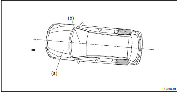
- Thrust angle
- Body center line
Thrust angle
γ = (α - β)/2
α: Rear RH wheel toe-in angle
β: Rear LH wheel toe-in angle
Substitute only the positive toe-in values from each wheel into α and β in the calculation.
- Front
- Body center line
READ NEXT:
 Cradle
A: REMOVAL
1) Set the vehicle on a lift.
2) Adjust the tilt position of the steering column to the lowest position and
lock the tilt lever.
3) Prevent the steering wheel from turning using the seat
Front Stabilizer
A: REMOVAL
1) Lift up the vehicle, and then remove the left and right front wheels.
2) Remove the front under cover. <Ref. to EI-35, REMOVAL, Front Under Cover.>
3) Remove the center exhaust p
Front Ball Joint
A: REMOVAL
1) Lift up the vehicle, and then remove the front wheels.
2) Remove the left and right stabilizer brackets.
3) Remove the ball joint.
Extract the cotter pin (a) from the ball stud.
Rem
SEE MORE:
Cooling fan, hose and connections
Your vehicle employs an electric cooling fan which is thermostatically controlled
to operate when the engine coolant reaches a specific temperature.
If the radiator cooling fan does not operate even when the coolant temperature
high warning light illuminates, the cooling fan circuit may be defe
Basic Diagnostic Procedure of Parking Brake
A: PROCEDURE
CAUTION: When removing or installing, remove all foreign matter (dust, water, and oil) from the electronic parking brake control module connectors.
NOTE:
To check the harness for open or short circuits, shake problem spot or connector.
Refer to "Check List for Inte
