Subaru Outback (BR): General Description of Drive Shaft System
Subaru Outback (BR) 2010-2015 Service Manual / Chassis / Drive Shaft System / General Description of Drive Shaft System
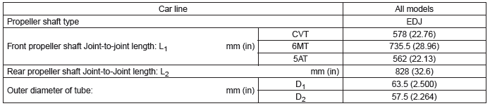
A: SPECIFICATION
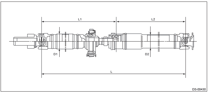
1. PROPELLER SHAFT
2. FRONT DRIVE SHAFT ASSEMBLY

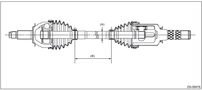
- Axle diameter
- Axle length
3. REAR DRIVE SHAFT ASSEMBLY

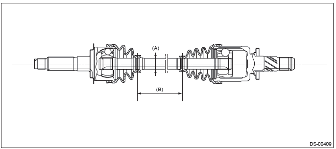
- Axle diameter
- Axle length
B: COMPONENT
1. PROPELLER SHAFT
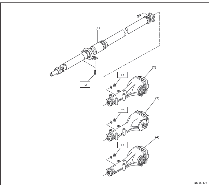
- Propeller shaft
- Rear differential (VA1-type)
- Rear differential (T-type)
- Rear differential (VA2-type)
Tightening torque: N*m (kgf-m, ft-lb)
T1: 31 (3.16, 22.9)
T2: 52 (5.3, 38.4)
2. FRONT AXLE
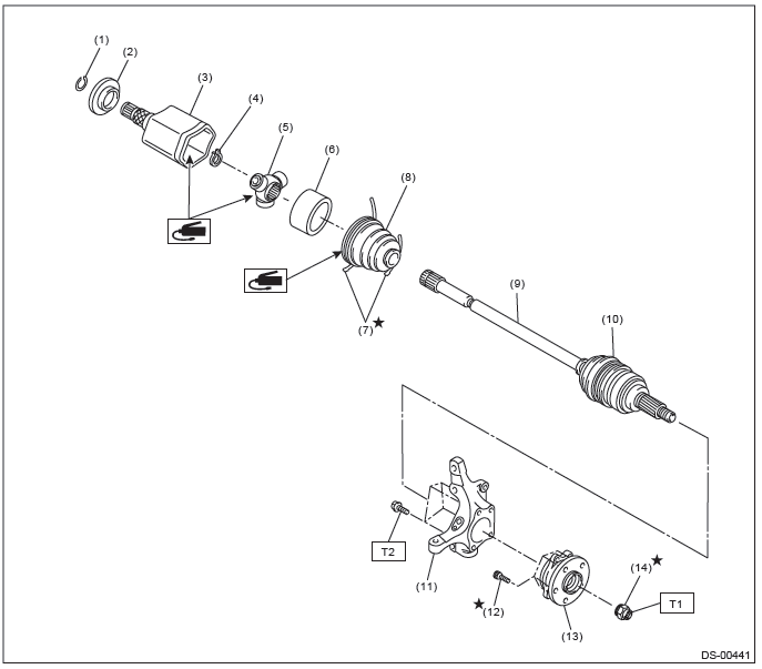
- Circlip
- Baffle plate
- Outer race (AAR)
- Snap ring
- Trunnion
- Grommet
- Boot band
- Boot (AAR)
- AC shaft ASSY
- Boot (AC)
- Front axle housing
- Hub bolt
- Front hub unit bearing
- Axle nut
Tightening torque: N*m (kgf-m, ft-lb)
T1: 220 (22.43, 162.3)
T2: 65 (6.63, 47.9)
3. REAR AXLE
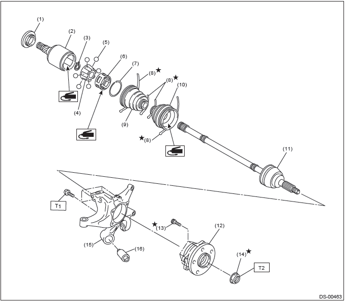
- Baffle plate
- Outer race (DOJ)
- Snap ring
- Inner race
- Ball
- Cage
- Snap ring
- Boot band
- Boot (DOJ)
- Boot (BJ)
- BJ shaft ASSY (sedan CVT model)
EBJ shaft ASSY (except for sedan CVT model) - Rear hub unit bearing
- Hub bolt
- Axle nut
- Rear axle housing
- Rear bushing
Tightening torque:N*m (kgf-m, ft-lb)
T1: 65 (6.63, 47.9)
T2: 240 (24.47, 177.0)
C: CAUTION
- Wear appropriate work clothing, including a helmet, protective goggles and protective shoes when performing any work.
- Remove contamination including dirt and corrosion before removal, installation or disassembly.
- Keep the disassembled parts in order and protect them from dust and dirt.
- Before removal, installation or disassembly, be sure to clarify the failure. Avoid unnecessary removal, installation, disassembly and replacement.
- Vehicle components are extremely hot after driving. Be wary of receiving burns from heated parts.
- Use SUBARU genuine grease etc. or equivalent. Do not mix grease etc. of different grades or manufacturers.
- Be sure to tighten fasteners including bolts and nuts to the specified torque.
- Place shop jacks or rigid racks at the specified points.
- Apply grease onto sliding or revolving surfaces before installation.
- Before installing snap rings, apply sufficient amount of grease to avoid damage and deformation.
- Before securing a part on a vise, place cushioning materials such as wood blocks, aluminum plates, or waste cloth between the part and the vise.
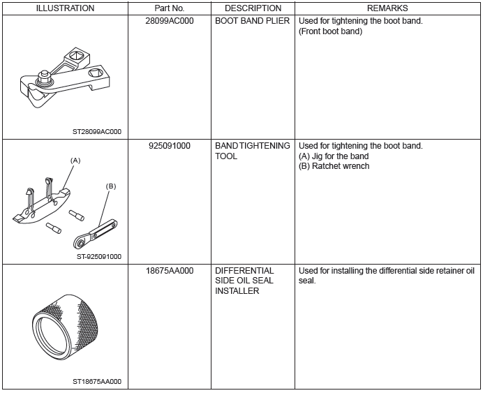
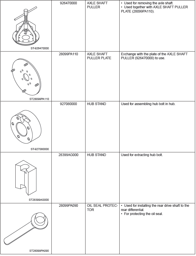
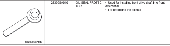
D: PREPARATION TOOL
1. SPECIAL TOOL
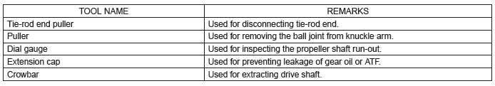
2. GENERAL TOOL
READ NEXT:
 Propeller Shaft
A: REMOVAL
CAUTION:
Do not disassemble the center EDJ of the propeller shaft.
Before removing propeller shaft, wrap the metal parts attached to the
rubber boot of center EDJ
with a cloth or rubb
Front Axle
A: REMOVAL
1) Lift up the vehicle, and then remove the front wheels.
2) Remove the axle nut.
CAUTION:
Do not loosen the axle nut while the front axle is loaded. Doing so may damage
the hub bearing.
Front Hub Unit Bearing
A: REMOVAL
1) Lift up the vehicle, and then remove the front wheels.
2) Remove the axle nut.
CAUTION:
Do not loosen the axle nut while the front axle is loaded. Doing so may damage
the hub bearing.
SEE MORE:
General Description of Differentials
A: SPECIFICATION
1. REAR DIFFERENTIAL
When replacing a rear differential assembly, select the correct one according to the following table.
NOTE:
Using a different rear differential assembly will cause the drive train and tires to drag or emit abnormal noise.
For option code, refe
Floor mat
Retaining pins are located on the driver’s side floor.
The floor mat is secured using the built-in grommets, by placing the grommets
over the pins and pushing them downward.
CAUTION
Make sure the driver’s floor mat is placed back in its proper location and correctly
secured on its ret
© 2010-2026 Copyright www.suoutback.com
