Subaru Outback (BR): General Description of Brakes
A: SPECIFICATION
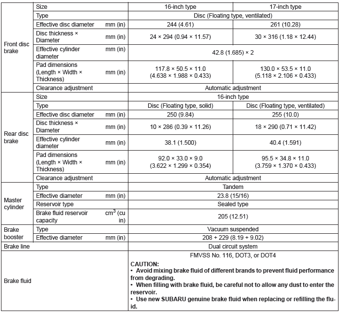
NOTE: Refer to "PB" section for parking brake specifications. <Ref. to PB-2, SPECIFICATION, General Description.>
B: COMPONENT
1. FRONT DISC BRAKE
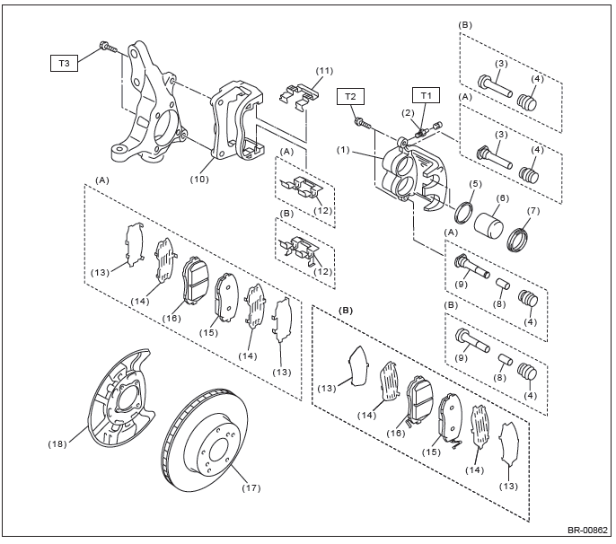
- 16-inch type
- 17-inch type
- Caliper body
- Air bleeder screw
- Guide pin (black)
- Pin boot
- Piston seal
- Piston
- Piston boot
- Bushing
- Lock pin (silver)
- Support
- Pad clip upper
- Pad clip lower
- Outer shim
- Inner shim
- Pad (outside)
- Pad (inside)
- Disc rotor
- Disc cover
Tightening torque: N*m (kgf-m, ft-lb)
T1: 8 (0.82, 5.9)
T2: 27 (2.75, 19.9)
T3: 120 (12.24, 88.5)
2. REAR DISC BRAKE
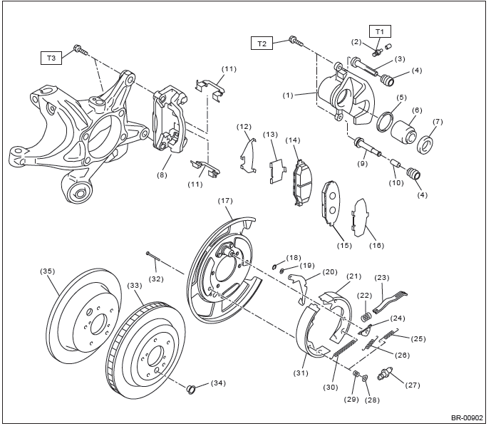
- Caliper body
- Air bleeder screw
- Guide pin (black)
- Pin boot
- Piston seal
- Piston
- Piston boot
- Support
- Lock pin (silver)
- Bushing
- Pad clip
- Outer shim
- Inner shim
- Inner pad
- Outer pad
- Shim
- Back plate
- Retainer
- Wave washer
- Lever
- Parking brake shoe (secondary)
- Strut spring
- Strut
- Shoe guide plate
- Secondary shoe return spring
- Primary shoe return spring
- Adjusting screw
- Shoe hold-down cup
- Shoe hold-down spring
- Adjusting spring
- Parking brake shoe (primary)
- Shoe hold-down pin
- Disc rotor (ventilated type)
- Adjusting hole cover
- Disc rotor (solid type)
Tightening torque: N*m (kgf-m, ft-lb)
T1: 8 (0.82, 5.9)
T2: 27 (2.75, 19.9)
T3: 66 (6.73, 48.7)
3. MASTER CYLINDER
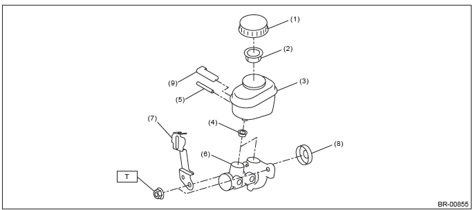
- Cap
- Filter
- Reservoir tank
- Seal
- Pin
- Cylinder body ASSY
- Bracket
- Seal sub ASSY
- Level sensor
Tightening torque:N*m (kgf-m, ft-lb)
T: 13 (1.33, 9.6)
4. FRONT BRAKE PIPES AND HOSES
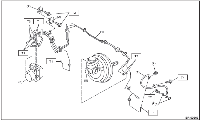
- Front brake pipe ASSY
- Two-way connector
- Front brake hose RH/LH
- Clamp
- Gasket
- VDC control module and hydraulic control unit (VDCCM&H/U)
- Bracket
- Master cylinder
Tightening torque:N*m (kgf-m, ft-lb)
T1: 15 (1.53, 11.1)
T2: 18 (1.84, 13.3)
T3: 19 ( 1.94, 14.0)
T4: 33 (3.36, 24.3)
5. CENTER AND REAR BRAKE PIPES AND HOSES
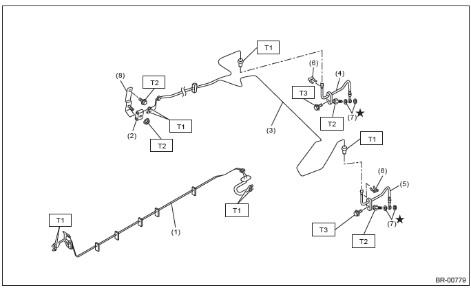
- Center brake pipe ASSY
- Connector
- Rear brake pipe ASSY
- Rear brake hose RH
- Rear brake hose LH
- Clamp
- Gasket
- Bracket
Tightening torque:N*m (kgf-m, ft-lb)
T1: 15 (1.53, 11.1)
T2: 18 (1.84, 13.3)
T3: 33 (3.36, 24.3)
6. BRAKE BOOSTER
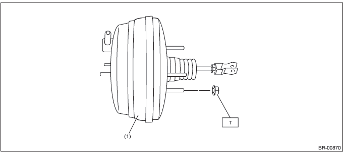
- Brake booster
Tightening torque:N*m (kgf-m, ft-lb)
T: 18 (1.84, 13.3)
7. BRAKE PEDAL
- AT model
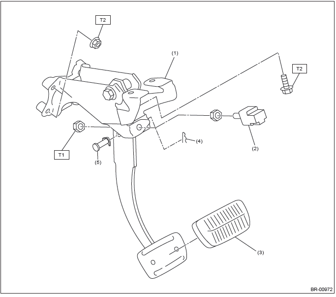
- Brake pedal ASSY
- Stop light switch
- Brake pedal pad
- Snap pin
- Clevis pin
Tightening torque:N*m (kgf-m, ft-lb)
T1: 8 (0.82, 5.9)
T2: 18 (1.84, 13.3)
- MT model
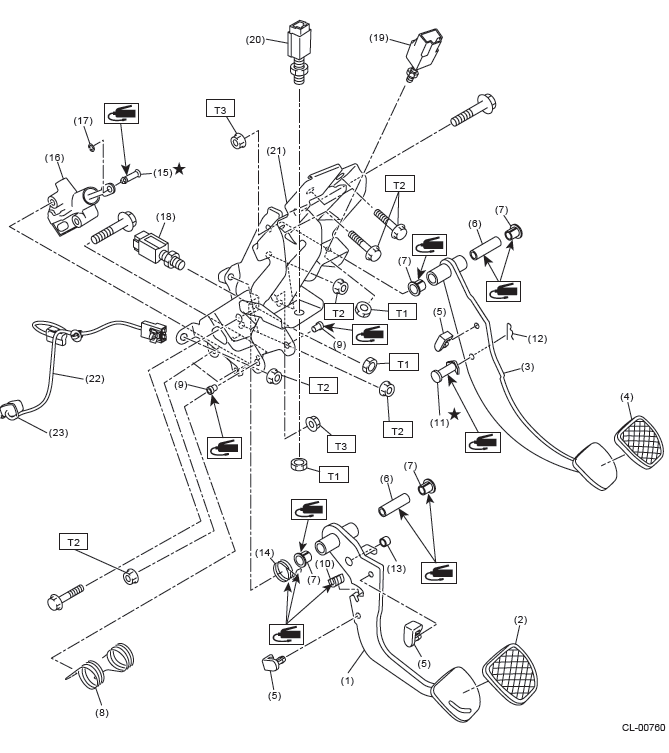
- Clutch pedal
- Clutch pedal pad
- Brake pedal
- Brake pedal pad
- Stopper
- Spacer
- Bushing
- Torsion spring
- Assist bushing
- Torsion spring bushing
- Clevis pin
- Snap pin
- Bushing A
- Assist spring
- Clevis pin
- Master cylinder ASSY
- Clip
- Clutch switch (clutch start)
- Stop & brake switch
- Clutch switch (cruise control)
- Pedal bracket
- Sensor harness
- Band
Tightening torque:N*m (kgf-m, ft-lb)
T1: 8 (0.82, 5.9)
T2: 18 (1.84, 13.3)
T3: 30 (3.06, 22.1)
C: CAUTION
- Wear appropriate work clothing, including a helmet, protective goggles and protective shoes when performing any work.
- Before removal, installation or disassembly, be sure to clarify the failure. Avoid unnecessary removal, installation, disassembly and replacement.
- Use SUBARU genuine grease etc. or equivalent. Do not mix grease etc. of different grades or manufacturers.
- Before securing a part on a vise, place cushioning material such as wood blocks, aluminum plate, or cloth between the part and the vise.
- Be sure to tighten fasteners including bolts and nuts to the specified torque.
- Place shop jacks or rigid racks at the specified points.
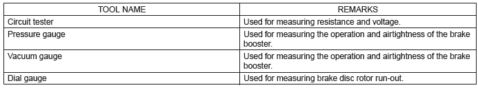
D: PREPARATION TOOL
1. GENERAL TOOL
READ NEXT:
 Front Brake Pad
A: REMOVAL
1) Lift up the vehicle, and then remove the front wheels.
2) Remove the front brake pad.
Remove the caliper bolt.
Raise the caliper body and support it.
NOTE:
Do not disconnect the bra
Rear Brake Pad
A: REMOVAL
1) Lift up the vehicle, and then remove the rear wheels.
2) Remove the rear brake pad.
Remove the bolts and remove the brake hose bracket.
Remove the caliper bolt, and raise and hold th
Brake Booster
A: REMOVAL
CAUTION:
Do not allow brake fluid to come in contact with the painted surface of the
vehicle body. If it does,
wash off with water and wipe away completely.
1) Disconnect the ground cable
SEE MORE:
Operation during cold weather
Carry some emergency equipment, such as a window scraper, a bag of sand, flares,
a small shovel and jumper cables. Check the battery and cables. Cold temperatures
reduce battery capacity. The battery must be in good condition to provide enough
power for cold winter starts.
Use an engine oil
Body Control System - List of Diagnostic Trouble Code (DTC)
A: LIST
Diagnostic Procedure with Diagnostic Trouble Code (DTC)
A: DTC B1100 INTEG. UNIT SYSTEM ERROR
DTC DETECTING CONDITION:
System error in body integrated unit
TROUBLE SYMPTOM:
LAN communication immobilizer function may not be executed normally.
B: DTC B1101 BATT P/SUPPLY MALFUNCTION
