Subaru Outback (BR): General Description of Rear Suspension
A: SPECIFICATION
Refer to "SPECIFICATIONS" in "FRONT SUSPENSION" section for rear suspension specifications. <Ref. to FS-2, SPECIFICATION, General Description.>
NOTE:
- Front toe-in, rear toe-in and front camber can be adjusted. Adjust if the value of toe-in or camber exceeds the tolerance range of the specification chart.
- Other items except for front toe-in, rear toe-in and front camber that are described in the specification chart cannot be adjusted. If other items exceed the tolerance range of the specification chart, check the suspension parts and connections for deformation. If defective, replace with new parts.
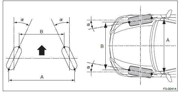
A - B = Positive: Toe-in, Negative: Toe-out
α = Individual toe angles
B: COMPONENT
1. REAR SUSPENSION
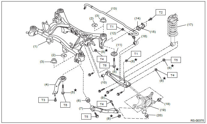
- Rear sub frame ASSY
- Rear sub frame stopper upper (except for OUTBACK model)
- Rear sub frame stopper upper (OUTBACK model)
- Front sub frame support plate
- Flange bolt A
- Trailing link bushing
- Trailing link
- Self-locking nut
- Flange bolt B
- Rear lateral link bushing
- Rear sub frame stopper lower
- Flange nut
- Rear stabilizer
- Stabilizer bushing
- Stabilizer clamp
- Stabilizer link
- Rear shock absorber ASSY
- Rear axle housing bushing
- Rear axle housing
- Trailing link rear bushing
Tightening torque: N*m (kgf-m, ft-lb)
T1: 33 (3.36, 24.3)
T2: 38 (3.87, 28.0)
T3: 70 (7.14, 51.6)
T4: 80 (8.16, 59)
T5: 120 (12.24, 88.5)
T6: 145 (14.79, 106.9)
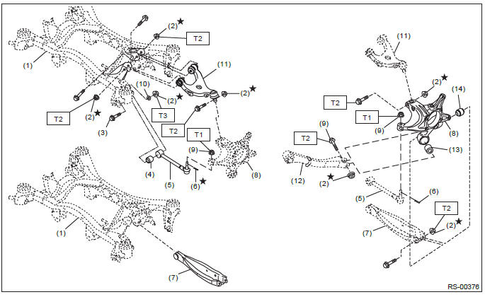
- Rear sub frame ASSY
- Self-locking nut
- Adjusting bolt
- Front lateral link bushing
- Front lateral link
- Snap pin
- Rear lateral link
- Rear axle housing
- Flange nut
- Adjusting washer
- Upper arm
- Trailing link
- Trailing link bushing
- Rear axle housing bushing
Tightening torque: N*m (kgf-m, ft-lb)
T1: 60 (6.12, 44.3)
T2: 80 (8.16, 59)
T3: 120 (12.24, 88.5)
2. REAR STRUT
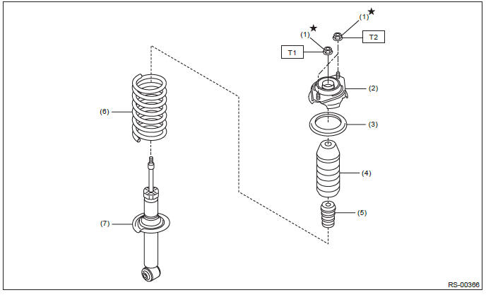
- Self-locking nut
- Upper rubber sheet
- Mount
- Dust cover
- Helper
- Coil spring
- Shock absorber
Tightening torque: N*m (kgf-m, ft-lb)
T1: 25 (2.55, 18.4)
T2: 30 (3.06, 22.1)
C: CAUTION
Please clearly understand and adhere to the following general precautions. They must be strictly followed to avoid minor or serious injury to the person doing the work or people in the area.
1. EACH PROCEDURE
- Wear appropriate work clothing, including a helmet, protective goggles and protective shoes when performing any work.
- Before disposing of shock absorbers, be sure to bleed the gas out completely. Also, do not expose to flames or fire.
- Before removal, installation or disassembly, be sure to clarify the failure. Avoid unnecessary removal, installation, disassembly and replacement.
- Use SUBARU genuine grease etc. or equivalent. Do not mix grease etc. of different grades or manufacturers.
- Before securing a part on a vise, place cushioning material such as wood blocks, aluminum plate, or cloth between the part and the vise.
- Be sure to tighten fasteners including bolts and nuts to the specified torque.
- Place shop jacks or rigid racks at the specified points.
2. OIL
When handling oil, adhere to the following to prevent unexpected accident.
- Prepare container and waste cloths when performing work which oil could possibly spill. If oil spills, wipe it off immediately to prevent from penetrating into floor or flowing outside, for environmental protection.
- Follow all government regulations concerning disposal of refuse when disposing.
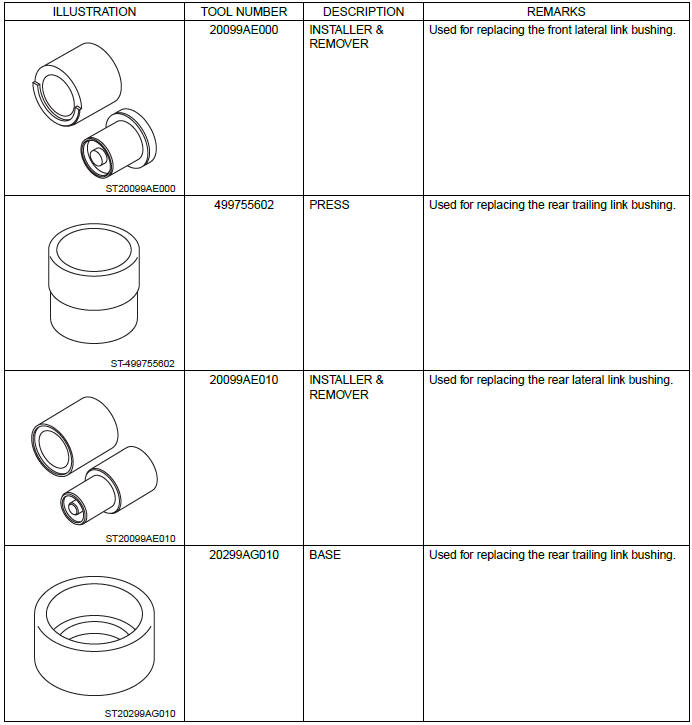
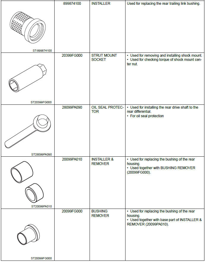
D: PREPARATION TOOL
1. SPECIAL TOOL
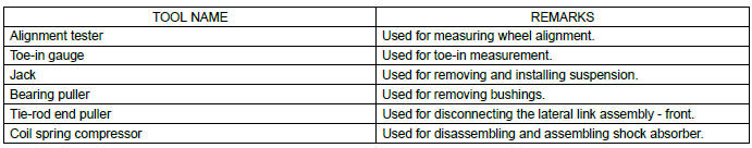
2. GENERAL TOOL
Wheel Alignment
A: INSPECTION
NOTE: Measure and adjust the front and rear wheel alignment at a time. Refer to "Wheel Alignment" in FS section for measurement and adjustment of wheel alignment.
- Inspection: <Ref. to FS-9, INSPECTION, Wheel Alignment.>
- Adjustment: <Ref. to FS-14, ADJUSTMENT, Wheel Alignment.>
READ NEXT:
 Rear Stabilizer
A: REMOVAL
1) Lift up the vehicle, and then remove the rear wheels.
2) Remove the rear stabilizer.
Remove left and right stabilizer links.
Detach the stabilizer clamp and remove the rear stabilize
Front Lateral Link
A: REMOVAL
1) Lift up the vehicle, and then remove the rear wheels.
2) Remove the trailing link.
Remove the bracket, and remove the parking brake cable from the guide
(a).
Remove the bolts and n
Wheel and Tire System
General Description
A: SPECIFICATION
Offset
P.C.D.
NOTE:
Size and inflation pressure of the standard equipment tire and spare tire for
emergency are described on the "Tire inflation pressure" l
SEE MORE:
Steering Gearbox
A: REMOVAL
1) Remove the cradle. <Ref. to FS-20, REMOVAL, Cradle.>
2) Remove the bolts, and remove left and right main mounting brackets.
3) Remove the bolts and remove the steering gearbox.
CAUTION:
Be careful not to damage the steering boot.
B: INSTALLATION
1) Before installation, check t
Choosing a child restraint system
Choose a child restraint system that is appropriate for the child’s age and size
(weight and height) in order to provide the child with proper protection. The child
restraint system should meet all applicable requirements of Federal Motor Vehicle
Safety Standards for United States or Canad
