Subaru Outback (BR): General Description of Vehicle Dynamics Control
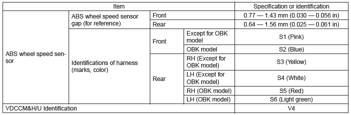
A: SPECIFICATION
B: COMPONENT
1. ABS WHEEL SPEED SENSOR
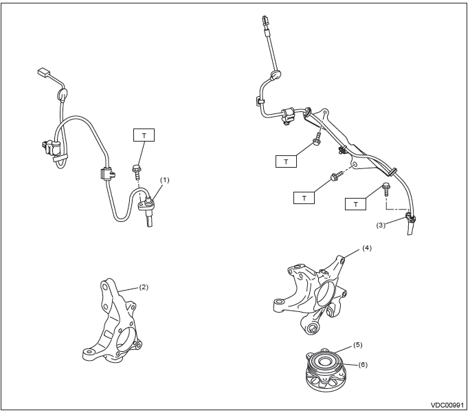
- Front ABS wheel speed sensor
- Front axle housing
- Rear ABS wheel speed sensor
- Rear axle housing
- Hub unit bearing
- Magnetic encoder
Tightening torque:N*m (kgf-m, ft-lb)
T: 7.5 (0.76, 5.5)
2. STEERING ANGLE SENSOR
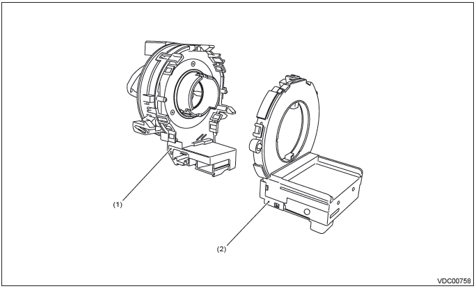
- Steering roll connector
- Steering angle sensor
3. VDC CONTROL MODULE & HYDRAULIC CONTROL UNIT (VDCCM&H/U)
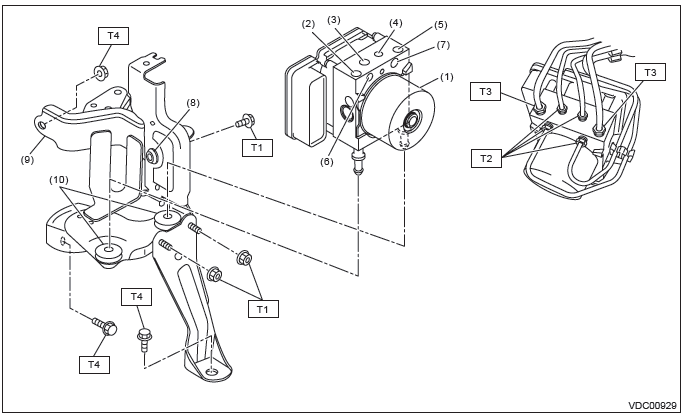
- VDC control module and hydraulic control unit (VDCCM&H/U)
- Secondary inlet
- Front LH outlet
- Front RH outlet
- Primary inlet
- Rear RH outlet
- Rear LH outlet
- Damper & spacer
- Bracket
- Damper
Tightening torque:N*m (kgf-m, ft-lb)
T1: 7.5 (0.76, 5.5)
T2: 15 (1.53, 11.1)
T3: 19 (1.94, 14.0)
T4: 33 (3.36, 24.3)
C: CAUTION
- Wear appropriate work clothing, including a helmet, protective goggles and protective shoes when performing any work.
- Remove contamination including dirt and corrosion before removal, installation or disassembly.
- Keep the disassembled parts in order and protect them from dust and dirt.
- Before disconnecting connectors of sensors or units, be sure to disconnect the ground cable from battery.
- Before removal, installation or disassembly, be sure to clarify the failure. Avoid unnecessary removal, installation, disassembly and replacement.
- Vehicle components are extremely hot after driving. Be wary of receiving burns from heated parts.
- Be sure to tighten fasteners including bolts and nuts to the specified torque.
- Place shop jacks or rigid racks at the specified points.
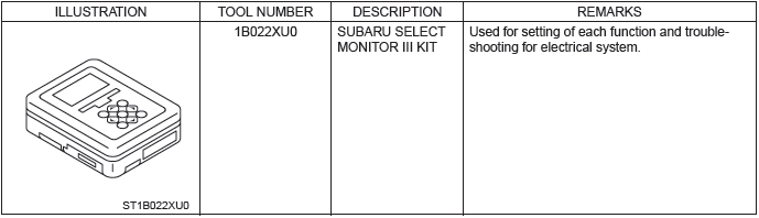
D: PREPARATION TOOL
1. SPECIAL TOOL
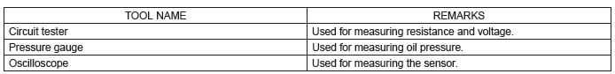
2. GENERAL TOOL
Relay and Fuse
A: LOCATION
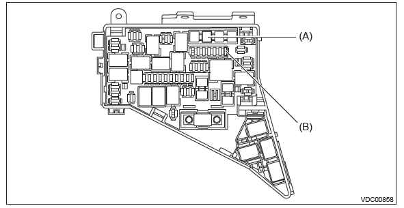

NOTE: For other related fuses, refer to the wiring diagram. <Ref. to WI-15, Power Supply Circuit.>
B: INSPECTION
1. CHECK FUSE.
1) Remove the fuse and inspect visually.
2) If the fuse is blown out, replace the fuse.
Vehicle Dynamics Control System
A: WIRING DIAGRAM
Refer to "Vehicle Dynamics Control System" in the wiring diagram. <Ref. to WI-251, WIRING DIAGRAM, Vehicle Dynamics Control System.>
B: ELECTRICAL SPECIFICATION
Refer to the Control Module I/O Signal of the "Vehicle Dynamics Control System (VDC) (DIAGNOSTICS)".
<Ref. to VDC(diag)-12, ELECTRICAL SPECIFICATION, Control Module I/O Signal.>
C: INSPECTION
Refer to the "Vehicle Dynamics Control System (VDC) (DIAGNOSTICS)". <Ref. to VDC(diag)-90, INSPECTION, General Diagnostic Table.>
D: NOTE
For operation procedures of each component of the vehicle dynamics control system, refer to the respective section.
- VDC control module & hydraulic control unit (VDCCM&H/U): <Ref. to VDC-9, VDC Control Module and Hydraulic Control Unit (VDCCM&H/U).>
- Yaw rate & G sensor: <Ref. to VDC-23, Yaw Rate and G Sensor.>
- Steering angle sensor: <Ref. to VDC-24, Steering Angle Sensor.>
- Front ABS wheel speed sensor: <Ref. to VDC-29, Front ABS Wheel Speed Sensor.>
- Rear ABS wheel speed sensor: <Ref. to VDC-32, Rear ABS Wheel Speed Sensor.>
- Front magnetic encoder: <Ref. to VDC-34, Front Magnetic Encoder.>
- Rear magnetic encoder: <Ref. to VDC-35, Rear Magnetic Encoder.>
- VDC OFF switch: <Ref. to VDC-36, VDC OFF Switch.>
READ NEXT:
 VDC Control Module and Hydraulic Control Unit (VDCCM&H/U)
A: REMOVAL
1) Disconnect the ground cable from battery.
2) Remove the air intake boot.
H4 model: <Ref. to IN(H4DOTC)-10, REMOVAL, Air Intake Boot.>
H6 model: <Ref. to IN(H6DO)-7, REMOVAL,
ABS Sequence Control
A: OPERATION
1) While the ABS sequence control is being performed, the operation of the
hydraulic unit can be checked using
the brake tester or pressure gauge after the hydraulic unit solenoid valve
Yaw Rate and G Sensor
A: NOTE
Yaw rate & longitudinal G and lateral G sensor are integrated with the VDC
control module & hydraulic control
module (VDCCM&H/U).
B: INSPECTION
1. YAW RATE & LONGITUDINAL G AN
SEE MORE:
Registering the phonebook data
1. Input the phone number to be registered. Refer to “Inputting the phone number”
F5-36.
2. Say the name to be registered.
3. “Confirm” is displayed.
4. Press the “TUNE/TRACK/CH” dial.
5. “Stored” is displayed.
6. Select “Speed Dial” by operating the “TUNE/TRACK/CH” di
DTC P0171, P0172, P0181, P0182, P0183, P0196, P0197, P0198, P0201, P0202,
P0203, P0204, P0222, P0223, P0301, P0302, P0303, P0304
AR:DTC P0171 SYSTEM TOO LEAN (BANK 1)
1. OUTLINE OF DIAGNOSIS
Detect fuel system malfunction by the amount of main feedback control.
Diagnostic method
Fuel system is diagnosed by comparing the target air fuel ratio calculated by
ECM with the actual air fuel ratio
measured by sensor.
2. ENABLE CONDI
