Subaru Outback (BR): Stop Light Switch
A: REMOVAL
1) Disconnect the ground cable from battery.
2) Remove the instrument panel lower cover.
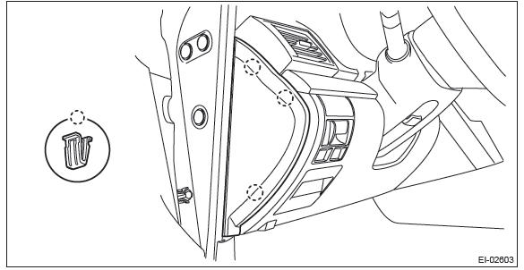
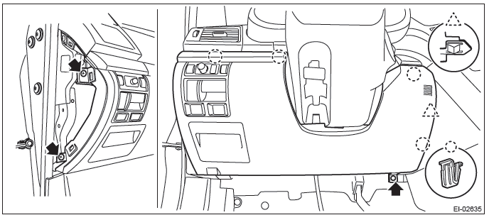
- Remove the clips, and remove the instrument panel side cover LH.
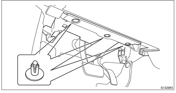
- Remove the clips and data link connector, and remove the instrument panel lower cover under.
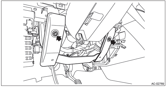
- Remove the bolts, and remove the knee guard panel.
- Remove the screws and clips and release the claws, and remove the instrument panel lower cover while disconnecting the harness connectors.
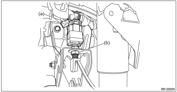
3) Remove the stop light switch.
- Disconnect the stop light switch connector (a).
- Remove the nut (b), and remove the stop light switch.
B: INSTALLATION
1) Install the stop light switch onto the bracket with screws and position it with the nut.
2) Adjust the stop light switch position, and then tighten the nut. <Ref. to BR-68, ADJUSTMENT, Stop Light Switch.>
3) Install each part in the reverse order of removal.
Tightening torque: Stop light switch: 8 N*m (0.82 kgf-m, 5.9 ft-lb)
C: INSPECTION
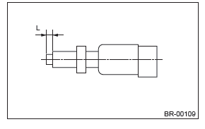
1. CHECK SPECIFIED POSITION
1) If the stop light switch does not operate properly or if it is not secured at the specified position, replace with a new part.
Specified position L: 2.8 mm+1.5 mm -0 mm (0.11 in+0.06 in -0 in)
2) Measure the clearance between the threaded end of the stop light switch and the stopper.
CAUTION: Be careful not to rotate the stop light switch.
Stop light switch clearance A: 0.8 mm (0.031 in)
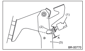
- Stop light switch
- Stopper
- Brake pedal
3) Adjust the position of the stop light switch if the inspection result is not within the standard value. <Ref. to BR-68, ADJUSTMENT, Stop Light Switch.>
2. CHECK RESISTANCE
1) Disconnect the stop light switch connector.
2) Measure the resistance between stop light switch terminals.
Preparation tool: Circuit tester
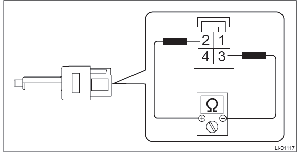

3) Replace the stop light switch if the inspection result is not within the standard value.
D: ADJUSTMENT
1) Loosen the lock nut, and adjust the stop light switch position until the clearance (A) between the threaded end of the stop light switch and stopper becomes 0.8 mm (0.031 in). Then, tighten the lock nut.
2) Tighten the lock nut.
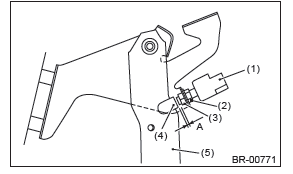
- Stop light switch
- Lock nut A
- Lock nut B
- Stopper
- Brake pedal
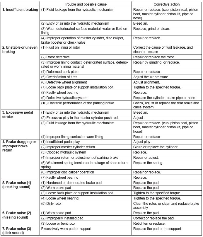
General Diagnostic Table
A: INSPECTION
READ NEXT:
 Parking Brake
General Description
A: SPECIFICATION
B: COMPONENT
1. PARKING BRAKE (REAR DISC BRAKE)
Back plate
Retainer
Lever
Parking brake shoe (Primary)
Parking brake shoe (Secondary)
Strut spring
Strut
Basic Diagnostic Procedure of Parking Brake
A: PROCEDURE
CAUTION: When removing or installing, remove all foreign matter (dust, water, and oil) from the electronic parking brake control module connectors.
NOTE:
To check the harness fo
SEE MORE:
To help prevent corrosion
Wash the vehicle regularly to prevent corrosion of the body and suspension components.
Also, wash the vehicle promptly after driving on any of the following surfaces.
● roads that have been salted to prevent them from freezing in winter
● mud, sand, or gravel
● coastal roads
Engine Control Module (ECM) I/O Signal
A: ELECTRICAL SPECIFICATION
Input/output name:
Crankshaft position sensor
Camshaft position sensor
Measuring condition:
After warming-up
At idling
Engine Condition Data
A: ELECTRICAL SPECIFICATION
Measuring condition:
After engine is warmed up.
Set the select lever in "P" range
