Subaru Outback (BR): Rear Drive Shaft, General Diagnostic Table
A: REMOVAL
1) Lift up the vehicle, and then remove the rear wheels.
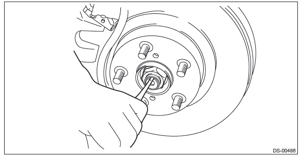
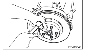
2) Remove the axle nut.
CAUTION: Do not loosen the axle nut while the rear axle is loaded. Doing so may damage the hub bearing.
- Lift the crimped section of axle nut.
- Remove the axle nut using a socket wrench while depressing the brake pedal.
3) Drain differential gear oil.
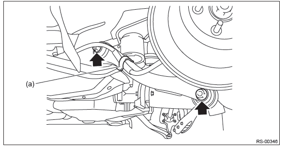
4) Remove the trailing link.
- Remove the bracket, and remove the parking brake cable from the guide (a).
- Remove the bolts and nuts, and then remove the trailing link.
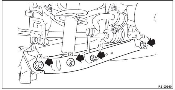
5) Remove the bolts and nuts and lower the rear lateral link.
- Remove the nut and disconnect the rear stabilizer link.
- Remove the shock absorber lower bolt.
- Disconnect the rear lateral link.
6) Remove the rear drive shaft from the rear differential.
- T-type
1. Fit the ST to the bolt (a) as shown in the figure.
CAUTION: Fit the ST to the bolts as shown in the figure to prevent damage of the side bearing retainer.
PREPARATION TOOL: ST: DRIVE SHAFT REMOVER (28099PA100)
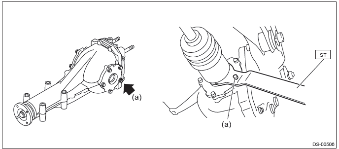
2. Extract the rear drive shaft from the rear differential.
- VA-type
1. Fit the tire lever (b) to the bolt (a) as shown in the figure.
CAUTION: To prevent damage to the side bearing retainer, use by placing the tire lever against the bolt as shown in the figure.
Preparation tool: Tire lever
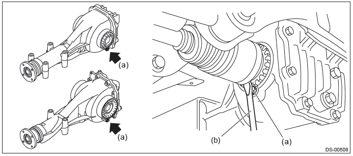
2. Extract the rear drive shaft from the rear differential.
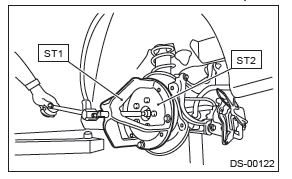
7) Remove the rear drive shaft from the rear axle.
NOTE: If it is hard to remove, use the ST.
PREPARATION TOOL:
ST1: AXLE SHAFT PULLER (926470000)
ST2: AXLE SHAFT PULLER PLATE (28099PA110)
B: INSTALLATION
1) Replace the rear differential side oil seal. <Ref. to DI-78, REPLACEMENT, Rear Differential Side Oil Seal.>
NOTE: After pulling out the drive shaft, be sure to replace with a new oil seal.
2) Insert the drive shaft into the rear hub spline, and pull the drive shaft into specified position.
CAUTION:
- Be careful not to damage the magnetic encoder.
- Do not get closer the tool which charged magnetism to magnetic encoder.
- Do not hammer drive shaft when installing it.
- Magnetic encoder
- Rear hub unit bearing
3) Tighten the axle nut temporarily.
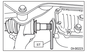
4) Using the ST, install the rear drive shaft to the rear differential.
PREPARATION TOOL: ST: OIL SEAL PROTECTOR (28099PA090)
5) Attach the links to the rear housing and tighten them to the specified torque.
Tightening torque:
Stabilizer link: 33 N*m (3.4 kgf-m, 24.3 ft-lb)
Shock absorber: 120 N*m (12.2 kgf-m, 88.5 ft-lb)
Rear lateral link: 80 N*m (8.2 kgf-m, 59 ft-lb)
Trailing link - rear sub frame: 120 N*m (12.2 kgf-m, 88.5 ft-lb)
Trailing link - rear housing: 80 N*m (8.2 kgf-m, 59 ft-lb)
6) While pressing the brake pedal, tighten the new axle nuts to the specified torque.
CAUTION: Do not load the rear axle before tightening the axle nut. Doing so may damage the hub bearing.
Tightening torque: 240 N*m (24.47 kgf-m, 177 ft-lb)
7) Lock the axle nut securely.
8) Fill differential gear oil.
9) Install the rear wheels.
Tightening torque: 120 N*m (12.24 kgf-m, 88.5 ft-lb)
10) Inspect the wheel alignment and adjust if necessary.
- Inspection: <Ref. to FS-9, INSPECTION, Wheel Alignment.>
- Adjustment: <Ref. to FS-14, ADJUSTMENT, Wheel Alignment.>
C: DISASSEMBLY
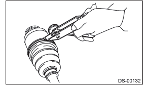
1) Take out the DOJ outer race from the shaft assembly.
CAUTION: Be careful not to damage the boot.
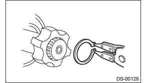
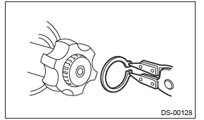
- Using a flat tip screwdriver or plier, loosen the boot band on the large end of DOJ boot.
CAUTION: Be careful not to damage the boot.
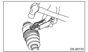
- Remove the boot band on the small end of DOJ boot in the same manner.
- Remove the large end of DOJ boot from DOJ outer race.
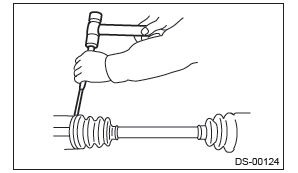
- Remove the round snap ring at the neck of DOJ outer race with a flat tip screwdriver.
- Take out the DOJ outer race from the shaft assembly.
- Wipe off the grease and take out the ball bearings.
CAUTION: The grease is a special grease (grease for constant velocity joints). Do not mix with other greases.
NOTE: Disassemble exercising care not to lose balls.
- Outer race
- Grease
2) Remove the cage from the inner race.
- Turn the cage by a half pitch to the track groove of inner race and shift the cage.
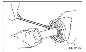
- Using pliers, remove the snap ring fixing the inner race to the shaft.
- Take out the DOJ inner race.
- Take off the DOJ cage from shaft and remove the DOJ boot.
CAUTION: Wrap shaft splines with vinyl tape to protect the boot from scratches.
3) Remove the BJ boot or EBJ boot in the same procedure as the DOJ boot.
NOTE: Further disassembly of the drive shaft is impossible because the BJ and EBJ cannot be disassembled.
D: ASSEMBLY
CAUTION: Wrap shaft splines with vinyl tape to protect the boot from scratches.
NOTE: Use specified grease.
BJ, EBJ side: NKG106
DOJ side: NKG205
1) Install the DOJ inner race to the shaft.
- Install the BJ or EBJ boot in specified position, and fill it with 50 to 60 g (1.76 to 2.12 oz.) of specified grease.
- Place the DOJ boot at the center of shaft.
- Insert the DOJ cage onto shaft.
- Cage
- Cutout portion
NOTE: Insert the cage with the cutout portion facing the shaft end, since the cage has an orientation.
- Install the DOJ inner race on shaft and fix the snap ring in place with pliers.
NOTE: Confirm that the snap ring is completely fitted in the shaft groove.
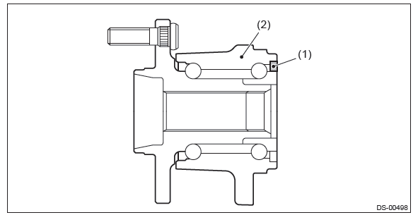
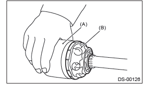
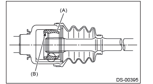
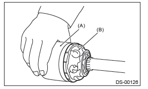
2) Install the cage to the inner race.
- Install the cage (B) with the protruding section aligned with the track on the inner race (A), and turn by a half pitch.
- Fill 80 to 90 g (2.82 to 3.17 oz) of specified grease into the inner side of the DOJ outer race.
- Apply a thin coat of specified grease to the cage pocket and ball.
- Insert the ball bearings into the cage pocket.
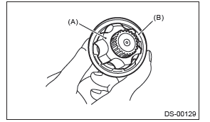
3) Connect the shaft assembly to the outer race.
- Align the outer race track and ball positions, and place the shaft, inner race, cage and ball bearings in the original positions, and then fix outer race in place.
- Outer race
- Grease
- Install the snap ring in the groove on the DOJ outer race.
CAUTION: Be careful of the following items during installation:
- Make sure that the balls, cage and inner race are completely fitted in the outer race of DOJ.
- Use care not to place the matched position of snap ring in the ball groove of outer race.
- Pull the shaft lightly and assure that the circlip is completely fitted in the groove.
- Apply an even coat of the specified grease [20 to 30 g (0.71 to 1.06 oz) ] to the entire inner surface of boot. Also apply grease to the shaft.
- Install the DOJ boot taking care not to twist it.
NOTE:
- The inside of the large end of DOJ boot and the boot groove shall be cleaned so as to be free from grease and other substances.
- When installing the DOJ boot, position the outer race of DOJ at center of the stroke.
- Put a new band through the clip and wind twice in the band groove of the boot.
- Pinch the end of band with pliers. Hold the clip and tighten securely.
NOTE: When tightening boot, use care so that the air within the boot is appropriate.
- Tighten the band using the ST.
PREPARATION TOOL: ST: BAND TIGHTENING TOOL (925091000)
NOTE: Tighten the band until it cannot be moved by hand.
- Tap the clip with the punch provided at the end of the ST.
PREPARATION TOOL: ST: BAND TIGHTENING TOOL (925091000)
NOTE: Tap to an extent that the boot underneath is not damaged.
- Cut off the band with an allowance of about 10 mm (0.39 in) left from the clip and bend this allowance over the clip.
CAUTION: Make sure that the end of the band is in close contact with clip.
4) Install the BJ boot or EBJ boot in the same procedure as a DOJ boot.
5) Extend and retract the DOJ repeatedly to provide an equal coating of grease.
E: INSPECTION
Check the removed parts for damage, wear, corrosion etc. Repair or replace if defective.
- DOJ (Double Offset Joint): Check for seizure, corrosion, damage, wear and excessive play.
- EBJ (high-efficiency compact ball fixed joint): Check for seizure, corrosion, damage, wear and excessive play.
- Shaft: Check for excessive bending, twisting, damage and wear.
- BJ (Bell Joint): Check for seizure, corrosion, damage and excessive play.
- Boot: Check for wear, warping, breakage and scratches.
- Grease: Check for discoloration and fluidity.
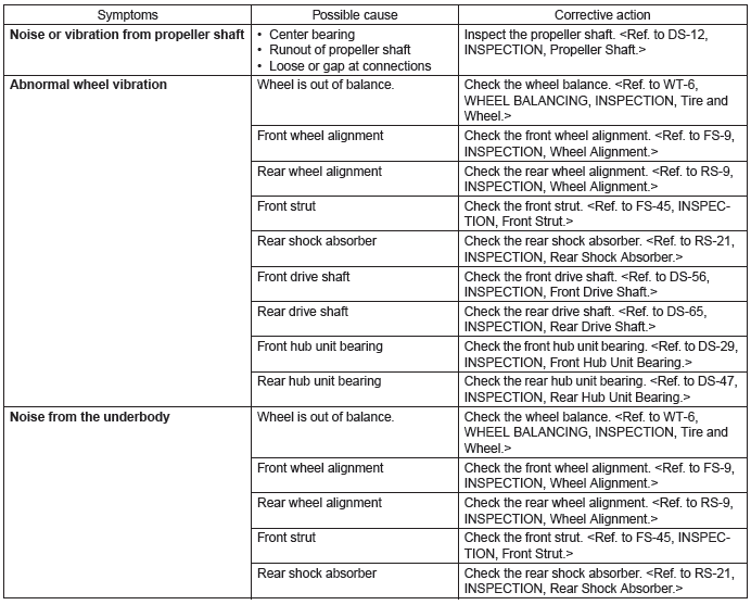
General Diagnostic Table
A: INSPECTION
NOTE: Vibration while cruising may be caused by an unbalanced tire, improper tire inflation pressure, improper wheel alignment, etc.
READ NEXT:
 General Description of Vehicle Dynamics Control
A: SPECIFICATION
B: COMPONENT
1. ABS WHEEL SPEED SENSOR
Front ABS wheel speed sensor
Front axle housing
Rear ABS wheel speed sensor
Rear axle housing
Hub unit bearing
VDC Control Module and Hydraulic Control Unit (VDCCM&H/U)
A: REMOVAL
1) Disconnect the ground cable from battery.
2) Remove the air intake boot.
H4 model: <Ref. to IN(H4DOTC)-10, REMOVAL, Air Intake Boot.>
H6 model: <Ref. to IN(H6DO)-7, REMOVAL,
SEE MORE:
Washing
CAUTION
● When washing the vehicle, the brakes may get wet. As a result, the brake stopping
distance will be longer. To dry the brakes, drive the vehicle at a safe speed while
lightly pressing the brake pedal to heat up the brakes.
● Do not wash the engine compartment and areas adj
Other markings
The following makings are also placed on the sidewall.
Maximum permissible inflation pressure
The maximum cold inflation pressure to which this tire may be inflated. For example,
“350 kPa (51 PSI) MAX. PRESS”
Maximum load rating
The load rating at the maximum permissible weight load for th
