Subaru Outback (BR): Select Lever (removal, installation, disassembly, inspection)
A: REMOVAL
1) Shift the select lever to "N" range.
2) Disconnect the ground cable from battery.
3) Lift up the vehicle.
4) Remove the rear exhaust pipe.
- 2.5 L non-turbo model <Ref. to EX(H4SO)-9, REMOVAL, Rear Exhaust Pipe.>
- 3.6 L model <Ref. to EX(H6DO)-8, REMOVAL, Rear Exhaust Pipe.>
5) Remove the heat shield cover.
6) Remove the cable from arm assembly.
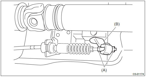
- Nut
- Arm ASSY
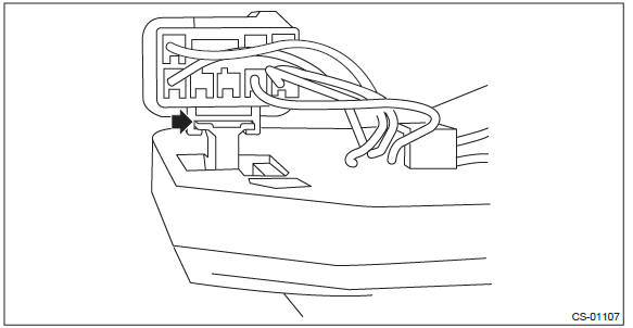
7) Raise the claw of clamp and remove the cable.
- Claw
8) Lower the vehicle.
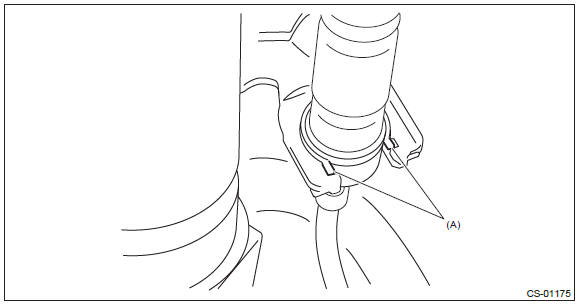
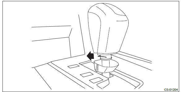
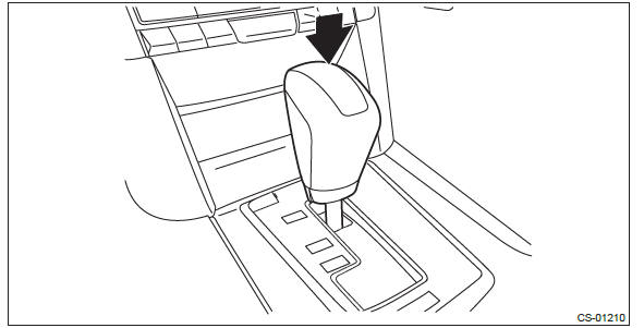
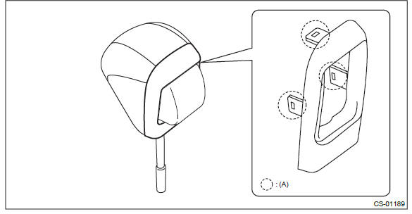
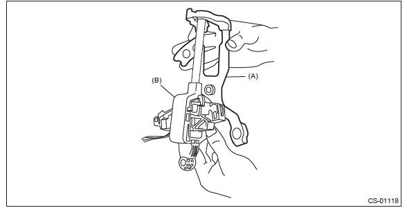
9) Lower the cover grip AT vertically toward the lever.
- Claws (3 places)
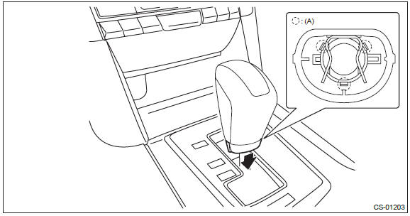
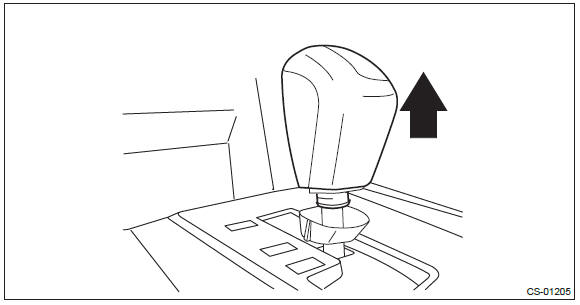
10) Remove the clamp grip pin.
11) Remove the grip assembly.
12) Turn over the rubber and remove the console front cover assembly.
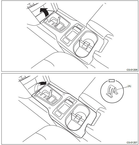
- Hooks (4 places)
13) Remove the console box. <Ref. to EI-73, REMOVAL, Console Box.>
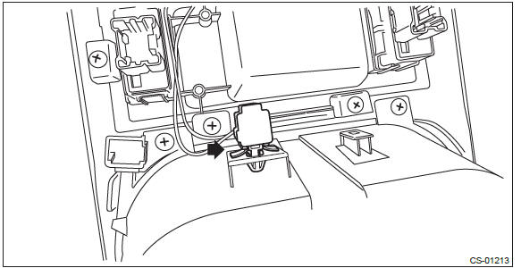
14) Remove the harness clip from the select lever.
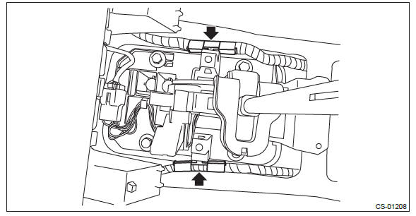
15) Disconnect the harness connector.
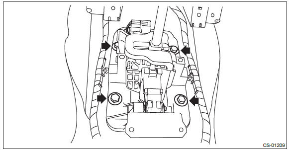
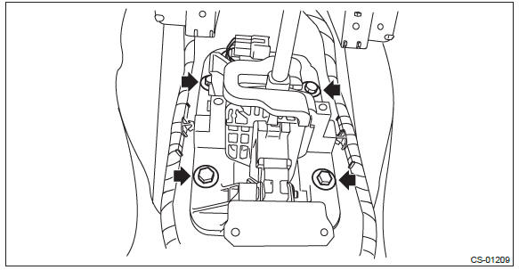
16) Remove the four bolts to remove the select lever assembly.
B: INSTALLATION
1) Set the select lever assembly to the vehicle body.
2) Tighten the four mounting bolts to attach the select lever assembly to the vehicle body.
Tightening torque: 18 N*m (1.8 kgf-m, 13.3 ft-lb)
3) Connect the harness connector.
4) Install the harness clip to the select lever assembly.

5) Shift the select lever to "N" range.
6) Install the console box and the console front cover assembly. <Ref. to EI-75, INSTALLATION, Console Box.>
7) Accessing from the button side of the grip, attach the clamp grip pin.
8) Install the cover grip AT securely.
NOTE: After installation, check that the cover grip AT cannot be detached.
9) Insert the grip assembly to the select lever and press it down until a click is heard.
10) After installation of grip, check the following points.
- The grip will not come off.
- The button on the grip operates normally.
11) Lift up the vehicle.
12) Shift the range select lever to "N" range.
13) Secure the cable to the bracket. <Ref. to CS-46, INSTALLATION, Select Cable.>
14) Adjust the select cable position. <Ref. to CS-50, ADJUSTMENT, Select Cable.>
15) After adjustment, confirm that the select lever operates properly at all range positions using the shift lock release button.
16) Install the heat shield cover.
Tightening torque: 18 N*m (1.8 kgf-m, 13.3 ft-lb)
17) Install the rear exhaust pipe.
- 2.5 L non-turbo model <Ref. to EX(H4SO)-9, INSTALLATION, Rear Exhaust Pipe.>
- 3.6 L model <Ref. to EX(H6DO)-8, INSTALLATION, Rear Exhaust Pipe.>
18) Inspect the following items. If a malfunction is found in the inspection, adjust the select cable or inhibitor switch (CVT model).
- The shift lock operates normally. <Ref. to CS-12, SHIFT LOCK OPERATION, INSPECTION, AT Shift Lock Control System.>
- Engine starts when the select lever is in "P" or "N" range, but not in other ranges.
- Back-up light illuminates when the select lever is in the "R" range, but not in other ranges.
- Select lever and indicator positions are matched.
C: DISASSEMBLY
1. GRIP ASSY
1) Remove the cover grip AT.
- Claws (3 places)
2) Remove the button assembly-AT.
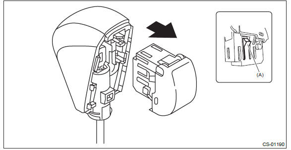
- Claw
3) Remove the rod COMPL.
2. AT SELECT LEVER ASSEMBLY
1) Remove the spacer plate.
2) Remove the gasket.
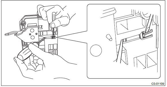
3) Insert a flat tip screwdriver with a thin tip under the connector and disconnect the harness connector from the plate COMPL.
4) Remove the harness from the plate COMPL.
5) Raise the claw with a flat tip screwdriver with a thin tip and remove the solenoid unit.
6) Using a flat tip screwdriver with a thin tip, remove the solenoid unit terminals from the connector.
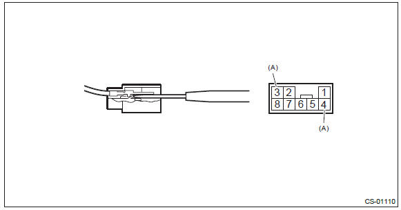
- Solenoid unit terminals
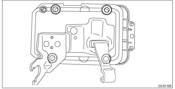
7) Remove the clamp push nut.
NOTE: Replace the clamp push nut with a new part.
8) Pull out shaft control.
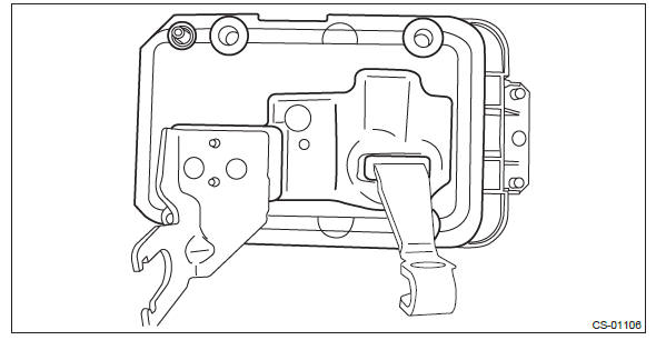
9) Remove the clamp push nut.
NOTE: Replace the clamp push nut with a new part.
10) Pull out spacer pin guide.
11) Remove the clamp pin.
12) Remove the spacer pin guide.
13) Remove the select lever COMPL from the plate COMPL.
14) Remove the arm assembly.
- Arm ASSY
- Selector lever COMPL
15) Remove the plate guide from the select lever COMPL.
16) Remove the rod detent and detent spring from the select lever COMPL.
3. INDICATOR ASSY
1) Disconnect the harness connector from the console front cover assembly.
2) Remove the four screws and remove the indicator assembly from the console front cover assembly.
D: ASSEMBLY
1) Clean all the parts before assembly.
2) Apply Multemp D or equivalent to the sliding portion of each part.
3) Assemble in the reverse order of disassembly.
NOTE: Insert the solenoid unit terminals to the harness connector.
- Solenoid unit (color code: blue)
- Solenoid unit (color code: black)
4) After installation, check the following points.
- The select indicator matches the select lever position when the select lever is changed from "P" range to "D" range.
- The select lever position and the position mark match each other.
- Operating force to move the select lever from "P" to "D" range.
E: INSPECTION
1) Inspect the removed parts by comparing with new ones for deformation, damage and wear. Repair or replace if defective.
2) Inspect the select lever assembly operating condition before assembly. Normal if it operates smoothly.
READ NEXT:
 Select Cable
A: REMOVAL
1) Shift the select lever to "N" range.
2) Disconnect the ground cable from battery.
3) Lift up the vehicle.
4) Remove the front exhaust pipe and rear exhaust pipe.
2.5 L model
<Re
MT Gear Shift Lever
A: REMOVAL
1) Disconnect the ground cable from battery.
2) Lift up the vehicle.
3) Remove the center exhaust pipe and rear exhaust pipe. (non-turbo model) <Ref.
to EX(H4SO)-8, REMOVAL,
Center Ex
MT Gear Shift Cable
A: REMOVAL
1) Disconnect the ground cable from battery.
2) Lift up the vehicle.
3) Remove the center exhaust pipe and rear exhaust pipe. (non-turbo model) <Ref.
to EX(H4SO)-8, REMOVAL,
Center Ex
SEE MORE:
Front Inner Remote
A: REMOVAL
1) Remove the door trim. <Ref. to EI-60, REMOVAL, Door Trim.>
2) Remove the screws to detach the front inner remote handle.
B: INSTALLATION
1) Before installation, check the following items.
Cable is free from deformation such as fray.
Grease is applied sufficiently to cable jo
Occupant Detection System (Diagnostics)
Basic Diagnostic Procedure
A: PROCEDURE
Check List for Interview
A: CHECK
General Description
A: CAUTION
1) If the seat cushion cover is removed or replaced,
make sure to perform the occupant detection system
adjustment after installing the seat to the vehicle.
<Ref. to OD(diag)-15, System Cal
